2.1 Light and physics⧉
Photography means writing with light. We need a working model of what light is and how it behaves, enough to follow it from a lamp, off a surface, through lenses, and into a camera. We need to understand how to model light and physical color, how to combine multiple light contributions, and how light can be routed through optical systems using reflection or refraction.
2.1.1 Light: rays, waves, and the spectrum⧉
There is no single right answer to "what is light." Physics offers three models (Figure 2.1.1), and the trick is to pick the one that makes the question at hand easy. When we want to know where light goes, through a pinhole, a lens, or off a mirror, we treat it as a ray, a straight line obeying simple geometry. When we want to understand color, diffraction, or interference, we treat it as a wave, a periodic disturbance with a wavelength. And when we want to count light precisely, which is what ultimately limits image quality, we treat it as a stream of photons, discrete particles whose random arrival creates noise. The three pictures are not contradictory; they are different limits of the same physics.
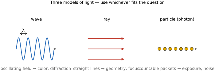
The wave picture and the spectrum. Light is an electromagnetic wave, a coupled oscillation of electric and magnetic fields that travels through vacuum at a fixed speed $c \approx 3 \times 10^{8}$ m/s (about 300,000 km/s, and slower by a factor $1/n$ inside a medium of refractive index $n$). A single-frequency, or monochromatic, wave is characterized by one wavelength $\lambda,$ the distance between successive crests, or equivalently by its frequency $\nu,$ the two tied by
Visible light occupies a narrow band, roughly 400 nm (violet) to 700 nm (red), a small part of the electromagnetic (EM) spectrum that also includes radio, microwave, infrared, ultraviolet, X-rays, and gamma rays, all the same physics, differing only in wavelength (Figure 2.1.2). "Visible" is a fact about our eyes, not about our cameras: a standard silicon sensor responds to wavelengths the eye cannot see, into the near infrared beyond 700 nm and, with the right optics, into the ultraviolet below 400 nm, and computational photography can put that extra reach to work (Sensors).
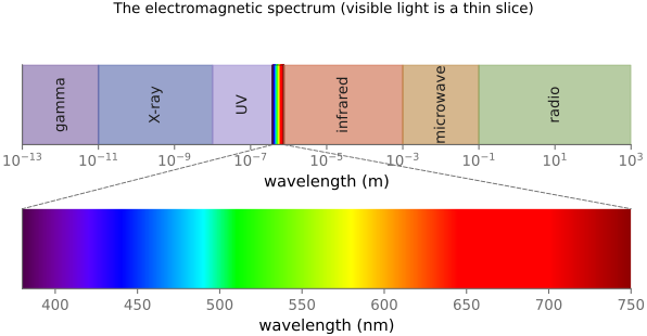
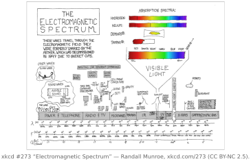
Most light is not monochromatic, however. A general wave is a superposition of many wavelengths, and what characterizes it is its spectrum: the distribution of energy over wavelength. That is, each wavelength has a given amount of energy, and this distribution characterizes the physical color of light. Physical color is different from the notion of color as perceived by humans, and the link between the two is fundamental in imaging; it is developed in the color chapter.
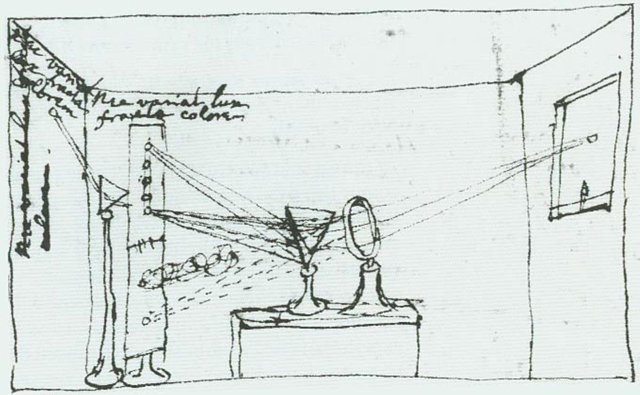
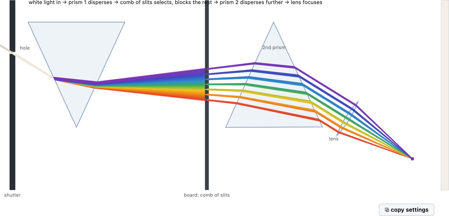
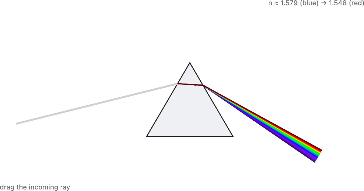
Newton's prism. Newton famously demonstrated the decomposition of white light into its spectrum. Pass a beam of white sunlight through a glass prism and it fans out into the full spectrum — the rainbow band of pure colors. The lesson is that white light is not a pure thing being "stained" by the glass; it is already a mixture of all wavelengths, and the prism merely bends each wavelength by a different amount, spreading the mixture out. Newton proved this with his experimentum crucis: he isolated one pure color from the spread and sent it through a second prism, and it did not split further. The pure colors are the irreducible ingredients; white is their sum (Figure 2.1.4).
 Isaac Newton (1642–1727) needs little introduction, but the prism is only the start of his presence in this book. The spectrum he split from white light is the physical basis of all the color science to come, and his Opticks established that color lives in the light, not the object. His corpuscular view of light competed for a century with the wave picture — both, we now know, are needed. On the mathematics side we still run Newton's method — step by the inverse curvature, $H^{-1}\nabla f$ — whenever a solver wants second-order convergence, and the Gauss–Newton refinement sits at the heart of feature tracking and bundle adjustment. Portrait: James Thornhill after Godfrey Kneller, 1689, public domain (via Wikimedia Commons).
So a spectrum is simply a function: power plotted against wavelength, $S(\lambda)$. You can think of it as an infinity of channels, one per wavelength.
Light, and the physical color it carries, is described by a spectral distribution: the power it carries at each wavelength, a function $S(\lambda)$. One wavelength is a single pure color; real light is a weighted mix of all of them. Everything downstream (how a prism fans light out, how a surface reflects it, how a sensor or an eye turns it into a perceived color) starts from this per-wavelength power.
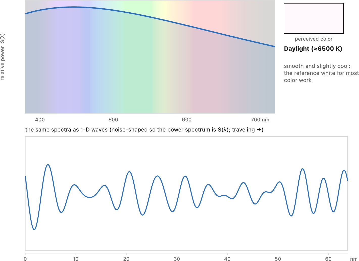
Spectra come in two broad flavors. A smooth spectrum varies gently with wavelength: daylight, an incandescent bulb, the glow of any hot body. A spiky spectrum piles its power into a few narrow lines with little in between: a fluorescent tube (sharp mercury lines on a faint phosphor background), many cheap LEDs, a sodium street lamp, a laser. As we will discuss, spiky illuminants tend to be bad for photography because they single out a few wavelengths: their color rendering is poor (skin tones and saturated fabrics shift unpredictably), they defeat a single white-balance correction, and a scene under them can look sickly even though a meter calls the light white. Smooth, broadband light (daylight, tungsten, good full-spectrum LEDs) is forgiving; spiky light is treacherous. We return to this with white balance, color rendering, and the design of a camera's color filters.
Photons. The third picture is granular: light arrives in discrete packets called photons, and a detector, a camera pixel or a cell in the eye, absorbs them one whole photon at a time. Wave and photon are the same light seen two ways. The wave tells you where the light goes and how bright it is, and its intensity (the square of the amplitude) is really the density of photon arrivals; the photon is what actually gets counted. Each photon's energy is set by the wave's frequency, $E = h\nu$ (with $h$ Planck's constant), so frequency is color: a blue photon (high frequency, short wavelength) carries more energy than a red one. We are simplifying here by giving each photon a single frequency, one pure wavelength; a real photon is a short wave packet with a small spread of wavelengths, but the one-frequency-per-photon picture is all photography needs. In this view the oscillation is not something a lone photon waves about in flight, it is the wave property that fixes the photon's color and energy, while the wave's amplitude sets how many photons show up. And because photons arrive at random, counting a finite number of them is inherently noisy, which is the shot noise that ultimately limits how clean an image can be.
2.1.2 How light is created⧉
Why do those spectra look the way they do? Light is emitted whenever electric charges accelerate, but the sources we photograph fall into a handful of physical processes, and each one stamps a characteristic spectrum. Knowing the mechanism tells you, before you ever meter the scene, whether a light will be smooth or spiky, warm or cool, and forgiving or treacherous to correct (Figure 2.1.7).
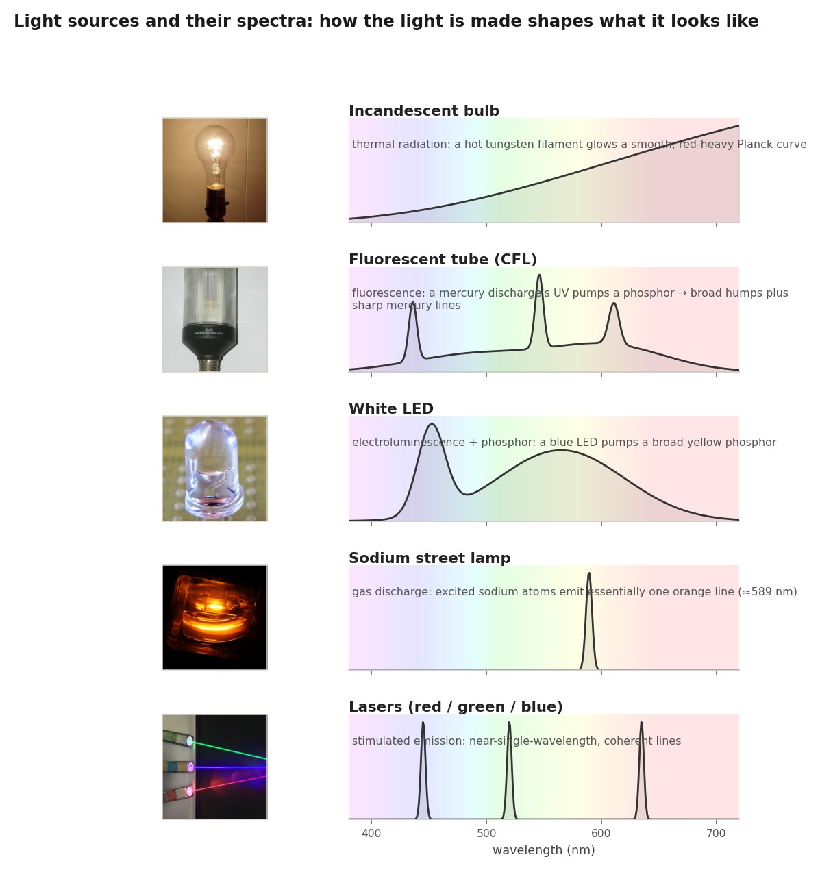
Each of those spectra is the fingerprint of a different way of making light, and it helps to watch the mechanisms actually run (Figure 2.1.8).
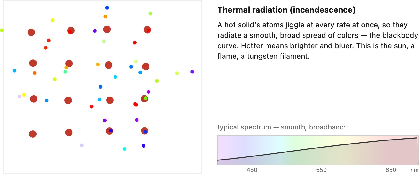
Thermal radiation (incandescence). Heat anything enough and it glows. A hot body emits the smooth, broadband blackbody spectrum, whose shape is set by temperature alone: as the object heats, the curve brightens and its peak slides from red toward blue. The sun (a ~5800 K surface), a tungsten filament (~2800 to 3200 K), a candle flame (sooty, ~1800 K) are all this same physics at different temperatures. That is exactly the color temperature axis, developed in the Illuminants section below. Thermal sources are always smooth and always red-heavy at the temperatures a filament can survive, which is why incandescent light looks warm. It is also wasteful: most of the radiated power is invisible infrared heat, not light. A halogen bulb is an incandescent filament with a halogen gas that redeposits evaporated tungsten back onto the wire, letting it run hotter (whiter, more efficient) and last longer, but it is still a hot filament throwing off a Planck curve.
Gas discharge (atomic emission lines). Run a current through a low-pressure gas and its atoms are kicked into excited states; each time an electron falls back it emits a photon at one precise wavelength, fixed by the spacing of that atom's energy levels. The result is a spiky spectrum of sharp lines with darkness in between. A low-pressure sodium street lamp is the extreme case: nearly all its light sits in a single orange doublet near 589 nm, which makes it very efficient but renders every color as a shade of orange-gray. Mercury vapor emits a few blue-green lines plus a lot of ultraviolet; neon glows red. These line spectra are the treacherous illuminants of the previous section: a camera's three filters cannot reconstruct what was never there between the lines.
Fluorescence (down-conversion). Line emission alone makes poor white light, so the fluorescent tube adds a trick: coat the glass with a phosphor that absorbs the mercury discharge's ultraviolet and blue and re-emits it as a broad glow at longer wavelengths (the Stokes shift, the same fluorescence discussed for surfaces below). The visible result is broad phosphor humps with the residual mercury lines still poking through, which is why a fluorescent spectrum is broad and spiky at once. This is the general recipe for turning invisible or narrow light into usable white: pump a phosphor and let it fluoresce.
Electroluminescence (LEDs). In a light-emitting diode, current drives electrons and holes together across a semiconductor junction, and each recombination releases a photon whose energy is set by the material's bandgap. That gives a fairly narrow band, a few tens of nanometers wide, and it does so far more efficiently than heating a filament. The catch is that one junction makes one color: a bare LED is red, or green, or blue, not white.
Making white from LEDs. There are two ways to build a white LED, and they mirror the two ways of making any white light. The first is an RGB triplet: put red, green, and blue LEDs side by side and let the eye sum them. The mix looks white and is electronically tunable, but its spectrum is three separated humps with gaps between, a metameric white with mediocre color rendering, and each color's brightness drifts differently with temperature and age, so the white wanders. The second, and now dominant, way is blue pump plus phosphor, which is fluorescence again: a bright blue LED excites a yellow phosphor that fluoresces over a broad band, and the leaked blue plus the re-emitted yellow add up to white. It is cheap and robust, but the raw version has a dip in the cyan and weak deep reds (a cool, sometimes harsh white); warm, high-fidelity LEDs add a red phosphor to fill that gap. The spectra of both a phosphor LED and a fluorescent tube appear in Figure 2.1.6.
Stimulated emission (lasers). One source stands apart. In a laser, an excited medium is made to emit in step, so the light is essentially a single wavelength and, crucially, coherent (the topic of the coherence section above). Lasers rarely light a scene directly, but they are the engine behind projectors, lidar, and the structured-light patterns used for depth sensing, and their coherence is what makes speckle and holography possible.
The thread through all of this: the emission mechanism fixes the spectrum, and the spectrum, smooth or spiky, is what decides how faithfully colors render and whether a single white-balance correction can ever set them right.
There is a second thread worth pulling, about where in the spectrum the energy lands. An incandescent bulb is mostly a heater: the bulk of its radiated power falls in the infrared, and only a few percent comes out as visible light. Modern sources reverse that. An LED or a fluorescent tube deliberately concentrates its emission inside the visible band, which is exactly why they are so much more efficient, an LED bulb makes the same visible light for a fraction of the wattage. That is the good news, and it is why they have taken over. The subtle bad news is for the photographer, or rather the sensor: silicon detectors keep responding well past 700 nm into the near infrared, where the eye sees nothing, and that near-IR sensitivity can be genuinely useful (low-light assist, some depth and material tricks, the near-IR imaging discussed with the sensor). But under efficient modern lighting there is simply very little near-IR light in the scene to work with, because the source has been engineered not to waste any there. The old, wasteful incandescent world was, ironically, a rich near-IR illuminant; the efficient one is nearly dark outside the visible. We return to this when we look at what sensors can see beyond the visible (Sensors).
2.1.3 Light power and brightness⧉
The wave perspective. We need to be precise about what we are actually measuring. The wave is an oscillating electric field $E(t)$, and for visible light that oscillation is fantastically fast: around $5\times10^{14}$ cycles per second. No sensor, and certainly no eye, can follow the field itself. What a detector responds to instead is the power the wave delivers, the rate at which it carries energy, and that power is proportional to the square of the field averaged over many oscillations, $\langle E^2\rangle$. A photodiode integrates the arriving energy, a rod or cone counts photons, a camera pixel accumulates charge in proportion to the light energy that lands on it during the exposure. In every case the measured quantity is a time-averaged power, or, multiplied by the exposure time, an energy, never the instantaneous field.
This time-averaged power is the quantity we will loosely call brightness or intensity throughout the book. It is worth fixing its character now, even though the precise radiometric quantities and units come a few pages on (radiance, irradiance, and exposure). Physically it is a power, energy per unit time, measured in watts; what a sensor cares about is the power per unit area falling on it, and multiplied by the exposure time that becomes the energy per area that actually forms the image. Two features of this quantity matter for everything that follows. Because it is a square, it is always non-negative. And because it is time-averaged, it throws away the instant-by-instant sign and phase of the field: a field $E(t)$ and its exact negative $-E(t)$ carry the identical power.
This makes brightness a quadratic quantity, built from the square of the field, and that is no technicality: it governs how two light contributions combine. You superpose the underlying fields, but what a detector reports is the square of their sum, and the square of a sum is not the sum of the squares. Whether the leftover cross term matters, so that two beams interfere rather than merely pooling their powers, is exactly the question of the next section.
What we call brightness or intensity is the power of the electromagnetic field, a quadratic quantity of the field. We never record the field itself, only its time-averaged square, so brightness is always non-negative and blind to the field's sign and phase. And because it is quadratic rather than linear in the field, two light contributions do not simply add in brightness: squaring their summed fields leaves a cross term, and whether that term survives or averages away is what coherence decides.
The particle perspective. The same power can be counted grain by grain. Light of frequency $\nu$ arrives as photons, each carrying a fixed packet of energy
where $h \approx 6.63\times10^{-34}$ J·s is Planck's constant (higher frequency, shorter wavelength, more energetic photon). The two pictures agree at the level of energy: the wave's time-averaged power is just this photon energy times the rate at which photons land. If a pixel collects $N$ photons of wavelength $\lambda$ over an exposure, the light energy it recorded is
So the brightness we built from $\langle E^2\rangle$ can equally be read as a photon flux, photons per second per unit area, each worth $hc/\lambda$. The wave tells you where that flux goes and how it interferes; the photon count tells you how finely it is quantized, and hence why a faint measurement is unavoidably noisy. And that is the picture that matters most for photography: in the end a camera does not measure a field, it counts photons, accumulating charge one photon at a time, so how many photons a pixel gathers during the exposure sets both the signal and, through their random arrival, the shot noise on top of it.
A few orders of magnitude make this concrete (all rough, good only to within a power of ten, counting visible photons at about $4\times10^{-19}$ J each):
| Situation | Photons (order of magnitude) |
|---|---|
| Direct summer sun, onto a surface | $10^{17}$ per cm² per second |
| Well-lit office (a few hundred lux) | $10^{15}$ per cm² per second |
| Clear starlit night | $10^{9}$ per cm² per second |
| Recorded by one pixel, well exposed | $10^{4}$ to $10^{5}$ per exposure |
| Recorded by one pixel, dim light | tens to hundreds per exposure |
| A household light bulb, all directions | $10^{19}$ per second |
| The Sun, all directions | $10^{45}$ per second |
Daylight to starlight already spans a hundred million to one, and photography has to work across all of it. Note how few photons actually land on a pixel: a well-exposed one holds only $10^{4}$ to $10^{5}$, and in dim light the count drops to tens or hundreds. At the source end the numbers run the other way, up to the Sun's $3.8\times10^{26}$ watts and its $10^{45}$ photons a second.
2.1.4 Summing coherent vs. incoherent light⧉
Optics, illumination, and imaging involves the combination of light contributions from different parts of a scene. This is makes it critical to understand the arithmetics of light: how do two light waves add? This is a rich question because the answer depends on the so-called coherence of the waves. On one end of the continuum lie coherent lights such as lasers that can interfere constructively or destructively, and on the other lie incoherent light like the sun or an incandescent light bulb that sum in averages. Coherence is a notion that applies to space and time and fundamentally deals with the correlation between two light waves or a light wave and itself.
When two waves overlap, the field a detector sees is the sum of the fields, $E_1+E_2$, because Maxwell's equations are linear in the field and fields simply superpose. But the brightness the detector reports is the average square of that sum,
The first two terms are just the individual brightnesses. The third is a cross term that can be positive, negative, or zero, so brightnesses do not simply add. Whether that cross term survives (the waves interfere) or averages away (their powers merely sum) is the entire content of coherence, which is where we turn next.
Two contributions are coherent when their phase difference is fixed and stays fixed long enough to matter, and incoherent when that phase difference drifts randomly and far faster than any sensor or eye can follow. A single-mode laser is the coherent extreme; sunlight, an incandescent bulb, and an LED are, for almost every everyday purpose, incoherent.
The distinction changes the arithmetic of combining light, and in a precise way: it changes which quantity is linear. In the coherent case the object that obeys superposition is the wave itself, the complex amplitude. You add the amplitudes of the contributions, and the brightness you measure is the squared magnitude of that sum. The cross terms in the square survive, and they are exactly interference: the bright and dark fringes where two coherent beams reinforce or cancel. A coherent optical system is therefore linear in amplitude; it convolves the incoming field with a complex point-spread function.
In the incoherent case the phases are scrambled and jitter through many full cycles during any real exposure, so when two contributions overlap their interference cross terms average to zero. What is left, and what adds, is intensity, the power. An incoherent system is linear in intensity: it convolves the incoming intensity with an intensity point-spread function, which is just the squared magnitude of the amplitude one. This intensity-linear picture, brightnesses that simply add and blur, is the one nearly all of this book runs on, and it is what makes imaging a tractable linear system (developed in Imaging as a linear system, where the same idea becomes the optical transfer function). Both regimes are linear; they are linear in different things, amplitude versus intensity, and that single difference is why interference shows up in one and not the other.
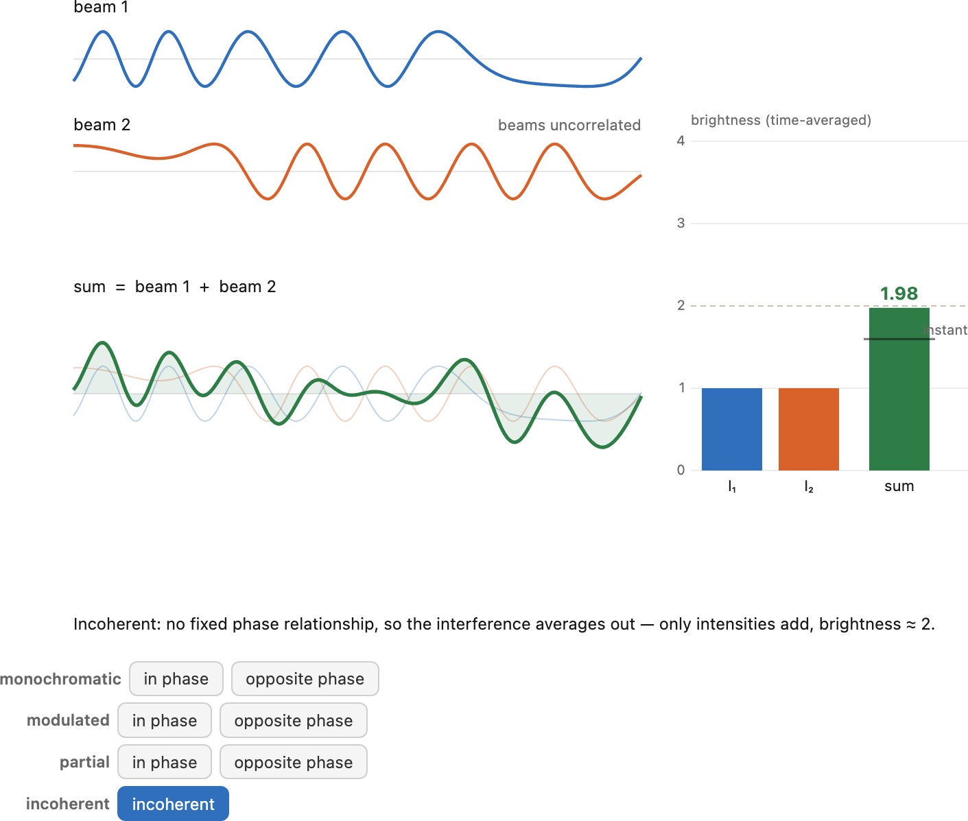
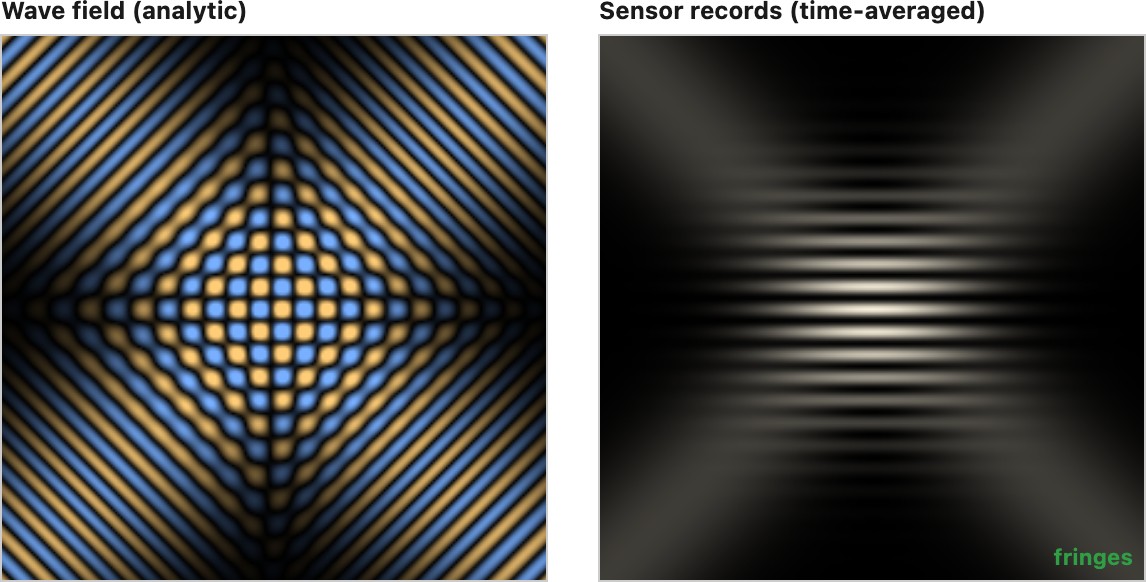
No real light is purely one or the other. Every source sits somewhere on a continuum of partial coherence, and where it sits depends on the scale, in both time and space, at which you look. Temporal coherence is tied to bandwidth: a wave stays in step with a delayed copy of itself only over a coherence length of about $\lambda^2/\Delta\lambda$ (equivalently $c/\Delta\nu$). For a narrowband laser this is meters; for broadband daylight it is only a few wavelengths, on the order of a micron, after which the wave forgets its own phase. Spatial coherence is tied to the source's angular size: light from a small or very distant source, a star, arrives with a well-defined wavefront across a wide patch, while light from an extended nearby source, the sun's disk or a softbox, is correlated only over a small coherence area. So even "incoherent" sunlight is perfectly coherent over a tiny patch and a sub-micron delay, and even a laser loses coherence over a long enough path or bandwidth. It is always a matter of degree and scale, never all or nothing.
A natural worry follows from all this talk of cancellation: if two beams can add up to darkness, where does their energy go? Nowhere; energy is conserved, and interference only redistributes it. Wherever two waves cancel they reinforce somewhere else, so the light missing from a dark fringe reappears in the bright ones and the total is unchanged. And when a wave is genuinely turned back, say reflected by the destructive interference engineered into an anti-reflection or high-reflection coating, the energy is not swallowed but returned, showing up as a back-pressure (radiation pressure) on whatever is driving the field: the antenna, the laser cavity, or the oscillating charges that launched it. Cancellation is bookkeeping about where the energy sits, never a loss of it.
This continuum is also what lets us get away with ray optics for most of the book. When light is effectively incoherent and its wavelength is tiny compared with the apertures and features it meets, the interference and diffraction terms wash out on average: contributions from different paths no longer reinforce or cancel, their intensities simply add, and energy flows along independent straight lines. That is precisely the picture of geometric optics and radiometry that the rest of this part is built on, radiance carried along rays, images formed by tracing rays, exposure as an integral of incident power. Ray optics is not a different theory of light; it is the incoherent, short-wavelength limit of wave optics, the regime in which the phase bookkeeping averages away and light behaves like independently added rays of energy. Push the other way, toward a narrow band, a small aperture, or a coherent source, and the wave nature reasserts itself: diffraction sets a hard resolution limit (later in this chapter), coherent illumination speckles, and holography and interferometry go to work on exactly the phase the ray picture discarded.
Coherence decides which quantity of light is linear. Coherent light superposes amplitudes, so its cross terms survive as interference; incoherent light superposes intensities, because the random phases average the cross terms away. No source is fully one or the other, only more or less coherent at a given scale of time and space. Ray optics is what emerges in the incoherent, short-wavelength corner of this space: interference washes out, intensities add along paths, and light travels as independent rays of energy. Most photography involves incoherent light, which means that it is linear in intensity.
This is not the last time a quadratic quantity will combine linearly only when the underlying contributions are uncorrelated. The same structure returns with sensor noise, where the quantity is not brightness but variance: the variances of independent noise sources add, so averaging $N$ independent frames divides the noise standard deviation by $\sqrt{N}$. Brightness here, variance there, different quantities carrying the same lesson, that squared quantities add linearly exactly when things are incoherent or independent. We will lean on it hard in the noise and denoising chapters.
The photon perspective. The same arithmetic has a clean reading in photons, and it is not the one people expect. Interference is not photons pushing on one another. Send light through two slits one photon at a time and each photon still lands in the fringe pattern; as Dirac put it, each photon interferes only with itself. The wave is a probability amplitude: for a single photon it encodes the contribution of every path it might take, and the chance of detecting the photon at a point is the squared magnitude of the summed amplitude. Coherent addition is that sum done before squaring, so the cross terms survive: a bright fringe is simply where a photon is very likely to land, a dark one where it almost never does. Nothing is destroyed at the dark fringes, the photons are only steered toward the bright ones, which is energy conservation restated as counting.
What makes light coherent or not, in this picture, is whether the paths are indistinguishable. If nothing, even in principle, could reveal which route (or which source) a photon took, the amplitudes add and interfere; the moment that information becomes available, the interference is gone and only the probabilities, the intensities, add. Independent sources are the incoherent extreme: their photons carry no fixed phase relationship and arrive as separate random events, so their counts simply pool, $1+1=2$, with no fringes. This is the same independence that governs noise. Photon arrivals are random and independent, so not only do their mean counts add, their variances add too, which is exactly the shot noise noted just above and the reason averaging $N$ independent frames cuts the noise by $\sqrt{N}$. Amplitudes when the paths are indistinguishable, intensities (and variances) when they are independent: the coherent versus incoherent split is, at bottom, a statement about what can be known about each photon.
2.1.5 Reflection, refraction, and what happens at a surface⧉
A central goal of imaging is to route light through a scene to the right place on a sensor. For this, we mostly deal with three types of interactions with matter and optical elements: reflection, refraction, and diffraction (Figure 2.1.11).
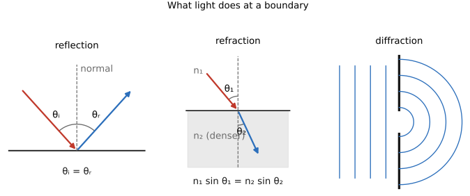
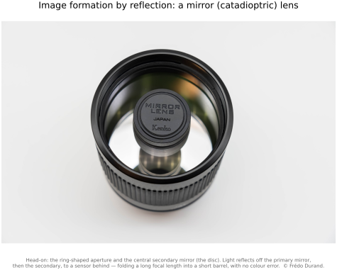
Reflection is the simplest: a ray striking a smooth surface bounces off so that the angle going out equals the angle coming in, both measured from the surface normal ($\theta_i = \theta_r$). That single rule explains mirrors and, as we will see, the bright highlights on shiny objects. Importantly, the reflection angle does not vary with wavelength, which is why mirror optics does not generate chromatic aberrations. There is a catch, though: reflection sends light back toward where it came from, so it is awkward to place a sensor there without occluding some of the incoming light. This is why telescopes and mirror (catadioptric) lenses usually carry a small secondary mirror in the middle that turns the light back the other way, through a hole in the primary, to a sensor tucked safely behind it (Figure 2.1.13).
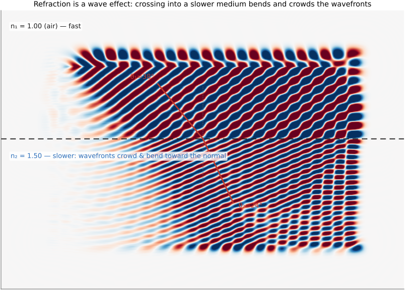
Refraction is what happens when light crosses from one medium into another, such as air into glass or air into water. Light travels more slowly in a denser medium, and the ratio of vacuum speed to the speed inside is the medium's refractive index $n$ (about 1.0 for air, 1.33 for water, 1.5 for typical glass). Because the wave slows, it bends. The reason is geometric: when a slanted wavefront reaches the boundary, the side that enters the denser medium first slows first and falls behind, so the whole wavefront pivots toward the slower side, the way a marching band wheels when the file on one end takes shorter steps (you can watch this unfold in Figure 2.1.14). The amount of bending follows Snell's law:
In that same simulation, the plane wave's wavefronts crowd together as they cross into the slower medium (the wavelength shortens by $1/n$) while bending toward the normal, so Snell's law emerges from the wave equation rather than being asserted. It is also the entire reason a lens works; the fuller lens geometry is deferred to the Lens image formation chapter, but the bending rule is the same one here. Diffraction, the spreading of a wave at a small aperture, is the third interaction, and because it sets a fundamental resolution limit it gets its own section at the end of this chapter. Reflection and refraction are naturally handled with ray optics and form the basis of lens design. Diffraction requires a wave perspective but is often a secondary issue in photographic optics, mostly boiling down to reducing sharpness when an aperture is too small.
At a boundary between two media, light bends by $n_1\sin\theta_1 = n_2\sin\theta_2$ — toward the normal entering a denser medium, away from it on the way out. This single rule is the seed of all lens optics: every focal length, every ray trace, the thin-lens equation, and every aberration is Snell's law applied at curved glass surfaces. Pair it with the fact that the index $n$ depends on wavelength (the next lesson) and you also get dispersion. Almost everything optical in this book traces back to it.
The name illustrates Stigler's law of eponymy: no scientific discovery is named after its original discoverer. The relationship was found, lost, and re-found across fifteen centuries:
- Ptolemy (c. 150 AD) measured air-to-water and air-to-glass refraction carefully and tabulated it, but fit the data to a quadratic that only works for small angles — close, but not the true law.
- Ibn Sahl (Baghdad, On Burning Instruments, 984 AD) had the correct law — stated as a constant ratio of lengths equivalent to the sine relation — and used it to design lenses that focus without aberration, more than six centuries before Europe. His was arguably the first true statement of refraction.
- Thomas Harriot (c. 1602) rediscovered the sine law experimentally in England but, as with much of his work, never published.
- Willebrord Snel van Royen (Snellius, 1621) derived it (in a cosecant form) in an unpublished manuscript found among his papers after his death — the source of the English name.
- René Descartes (Dioptrique, 1637) was the first to publish the law in its modern sine form, $n_1\sin\theta_1 = n_2\sin\theta_2$, alongside a (physically dubious) mechanical derivation. This is why the French still call it la loi de Descartes.
- Pierre de Fermat (1657–62), distrusting Descartes' reasoning, re-derived the same law from his principle of least time, the standard variational argument still taught today, and the one that ties back to the equal-optical-path view of why a lens focuses.
So the law that anchors this entire book is named after the man who left it in a drawer, was first written down correctly by Ibn Sahl, and was given its cleanest reason by Fermat. A fitting reminder that the tidy attributions in textbooks are usually a courtesy, not a history.
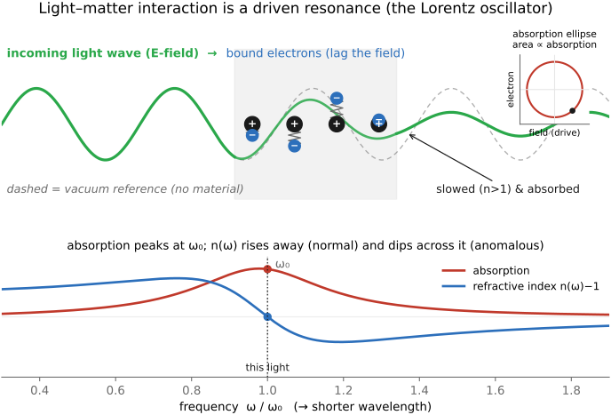
Light–matter interaction is largely resonance. It is worth pausing on why light slows in glass at all, why the index of refraction always depends on wavelength, and why different materials attenuate different wavelengths. It all comes down to vibration and resonance of the particles that make up matter. The wave's oscillating electric field drives the bound charges in a material, such as atoms, molecules, and electrons bound to nuclei, and like any spring-loaded mass each has a natural frequency it most readily oscillates at. This can be modeled as a so-called Lorentz-oscillator, and almost everything optical follows from it. Near a resonance frequency, the driven charges swing hard and the material absorbs strongly, draining those wavelengths from the light; the wavelengths a material happens to absorb (and so remove from what it transmits or reflects) are exactly what give it its color. The same driven-charge picture runs far below light too: a microwave oven cooks by driving the water molecules in food with an oscillating field they cannot quite keep up with, and that lag turns into heat (dielectric loss, the low-frequency cousin of optical absorption). Away from resonance the charges still respond, just out of step, and that lag is what slows the wave, so the refractive index $n$ is itself a resonance effect. Because each wavelength sits a different distance from the nearest resonance, $n$ varies with wavelength; this is dispersion, $n(\lambda)$, and it is behind the prism fanning out a spectrum (Figure 2.1.12), the colors of a rainbow, and the chromatic aberration that plagues real lenses. That last consequence is not a footnote: because every glass disperses, a simple lens focuses blue and red at slightly different distances, and dispersion goes on to shape much of the challenge of lens design — the whole craft of combining crown and flint glasses into achromatic and apochromatic doublets, and the modern fight against chromatic aberration in fast lenses, exists to fight exactly this $n(\lambda)$ (developed in the Optics part). The resonance picture can be explored directly (Figure 2.1.15): the bound electron is driven at different frequencies, and the absorption peaks at resonance while the refractive index swings through its normal-then-anomalous dispersion.
The refractive index is not a constant: $n(\lambda)$ depends on wavelength — in ordinary glass it rises toward the blue, so blue bends more than red. Because of this you cannot route every wavelength the same way with a single refraction: a prism fans white light into a spectrum, a raindrop makes a rainbow, and a simple lens focuses blue and red at slightly different distances — chromatic aberration. Much of the craft of lens design (combining crown and flint glass into achromatic and apochromatic groups) exists to fight this one fact. Dispersion is not a defect of cheap glass; it is built into how matter and light interact.
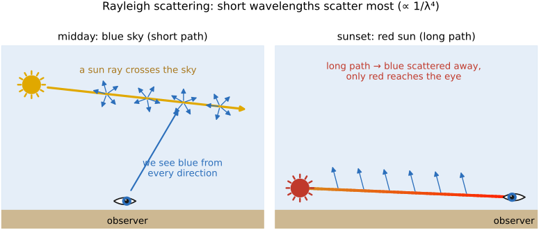
Both follow from Rayleigh scattering: air molecules are much smaller than the wavelength of light and scatter short (blue) wavelengths far more strongly than long (red) ones — the scattered fraction grows as $1/\lambda^4$, so blue (≈450 nm) scatters roughly ten times more than red (≈650 nm). At midday the sunlight takes a short path through the atmosphere; the blue it sheds is scattered out in every direction and reaches your eye from all over the sky, so the sky reads blue while the sun stays roughly white. At sunset the light skims a long, grazing path through the air; by the time it reaches you almost all its blue has been scattered away, and mostly orange and red survive — so the sun and the clouds near it redden (Figure 2.1.16). When the scattering particles are large compared to the wavelength — water droplets in fog or cloud — every wavelength scatters about equally (Mie scattering), which is why clouds and haze are white or gray, not blue. Minnaert, The Nature of Light and Colour in the Open Air One caveat the physics alone hides: the color you finally see is not in the scattered light by itself — "blue" and "orange" are your cones' verdict on these spectra, so the apparent color of the sky depends on the visual system reading it as much as on the scattering. The same sky spectrum read by a different eye is a different color — vividly so across species (→ the cross-species sky figure in Perceptual color and trichromatic vision Weiss & Springer 2026 (colour of the sky for a non-human)).
A rainbow is a caustic, a place where rays concentrate. It is tempting to explain it as "dispersion, like Newton's prism," but dispersion alone is not a rainbow: a prism merely fans white light into a spread, and a spread is not a bright arc pinned at a fixed angle. The brightness and the fixed 42° angle come from the geometry of the sphere; dispersion only supplies the colors. Each falling raindrop is a tiny sphere, and sunlight refracts in, reflects once off the back, and refracts out again (Figure 2.1.18, left).
The key geometry is this. Slide the entry point across the drop — the impact parameter — and the total deviation of the exiting ray sweeps down to a minimum (about 138° for water) and turns back up. Near that minimum the deviation is stationary, so rays entering at many different points all leave in almost the same direction: they bunch up, and that pile-up is the bright arc, seen at $180°-138° \approx$ 42° from the antisolar point (Figure 2.1.18, right). This is why the single internal reflection is essential — and why a ray that only refracts in and out, with no bounce, makes no rainbow at all: with two refractions only, the deviation grows monotonically with the impact parameter and never turns around, so there is no stationary angle for light to concentrate at. The primary bow is the one-bounce caustic at 42°; the fainter, color-reversed secondary bow is the two-bounce caustic, its own minimum putting it at about 51°. Only now does dispersion matter: because $n$ is a touch larger toward the blue, each color's caustic sits a degree or so from its neighbors, fanning the bunched light into the ordered band we see.
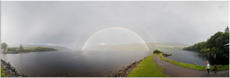
Between the two bows sits a conspicuously darker strip of sky, Alexander's band (named for Alexander of Aphrodisias, who described it around 200 AD). Its darkness follows directly from the caustic story: one-reflection light only ever emerges at 42° or less — it piles up at 42° and scatters out to fill the sky inside the primary bow — while two-reflection light only emerges at 51° or more, outside the secondary. The 42°–51° gap between them receives almost no rainbow light from either path, so it reads as a dark band, with brighter sky on both sides. You can see the whole story in a real double bow over Loch Ness (Figure 2.1.21): bright primary, fainter reversed secondary outside it, the dark band between, and the noticeably brighter sky inside the primary.
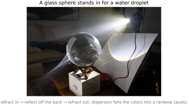
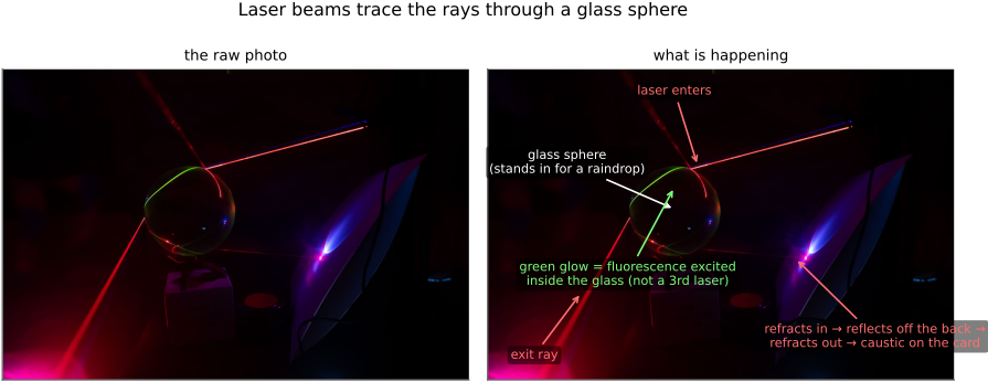
You can run the whole experiment on a workbench with a clear glass sphere standing in for a raindrop (Figure 2.1.19): a bright beam refracts in, reflects off the back, and throws a little rainbow caustic onto a card. Send narrow laser beams through the same sphere in a hazy room and the rays themselves become visible (Figure 2.1.20): you can watch each beam refract in, bounce off the back, and refract out — the exact refract–reflect–refract path the diagram traces. The rainbow in the sky is just this single-drop geometry, summed over a skyful of drops. Minnaert, The Nature of Light and Colour in the Open Air
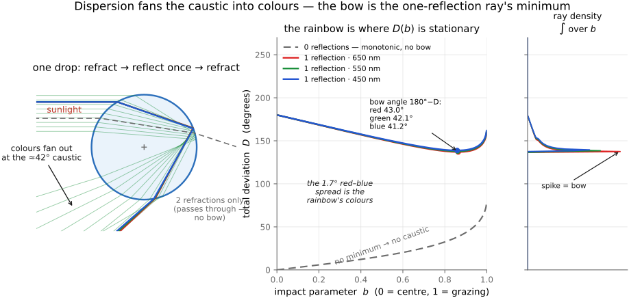
Why a drop makes a bow and a prism does not. Left: parallel sunlight enters a spherical water drop at different points, refracts, reflects once off the back, and exits bunched near the 42° rainbow ray — a caustic. A ray that only refracts through (no internal reflection) just passes on, turned but never concentrated. Middle: Descartes' construction — total deviation $D$ versus impact parameter $b$. The one-reflection curve has a minimum (≈138° → a bow at 42°); two reflections give the secondary (≈51°); the zero-reflection curve (two refractions only) is monotonic — no minimum, no caustic, no rainbow. Right: the same physics as an integral — the ray density as a function of deviation (summed over every impact parameter), which spikes exactly at the stationary deviation: that spike is the rainbow, and dispersion splits it into the three colored spikes shown. Interactive: it is a water drop; drag the impact parameter, choose the number of internal reflections, and tick "zoom near the caustic" to re-range both the slider and the plot tightly around the bow. Dispersion is always on, so the colors separate near the minimum.
Stands alone: a ray traced through a spherical drop beside the deviation-vs-impact-parameter plot, showing the rainbow as the stationary (minimum-deviation) angle of the one-internal-reflection ray, and no caustic for the two-refractions-only path.
Scattering and absorption in media. The same physics that paints the sky operates at close range whenever light travels through a participating medium such as fog, haze, smoke, or water. Light is scattered out of its straight path and absorbed along the way, so distant objects lose contrast and take on the color of the medium (the bluish veil of haze, the green-blue cast underwater). When light scatters only once before reaching the camera the effect is mild; multiple scattering through thick fog washes the scene out entirely. Undoing this — dehazing and de-weathering — is a recurring computational-photography problem, and it is built on exactly the scattering model sketched here.
Reflection versus refraction, for building optics. These two ways of redirecting light have complementary strengths, and the trade-off runs through all of lens and mirror design. Reflection's great advantage is that it is independent of wavelength: a mirror bends every color by exactly the same angle, so it introduces no chromatic aberration. Its drawback is geometric, because it sends light back the way it came: to catch the focused image you must place a sensor in the returning beam, where it sits in the path of the incoming light and blocks part of it. That is the central nuisance every reflecting (mirror) telescope has to engineer around. Refraction has the opposite profile. It merely bends light, which then carries on in roughly its original direction, so nothing has to sit in the incoming path. But it bends different wavelengths by different amounts, so a single lens focuses the colors in slightly different places, and forcing them all back to one point takes more, and more complex, glass (the long story of the OPTICS part).
2.1.6 Polarization⧉
Light is a transverse wave: its electric field oscillates perpendicular to the direction the light travels. How that oscillation is oriented over time is the light's polarization, and in general it is not a single fixed direction: the field can stay in one plane (linear polarization), rotate as the wave advances (circular or elliptical polarization), or have no preferred orientation at all. Natural light, from the sun or a bulb, is unpolarized: the field direction is a rapidly varying jumble with no single preferred orientation. But reflection off a non-metallic surface (water, glass, a wet road, foliage) partially polarizes the reflected light, biasing it toward one orientation. This is why a polarizing filter is so useful in photography: rotated to block that orientation, it cuts glare and reflections, lets you see into water, and deepens a blue sky (the sky's scattered light is partly polarized too). It is a physical effect you cannot replicate after the fact in software (forward-ref: the polarizer among the Photography 101 lens filters; reflection and specular removal in Single-image computational photography).
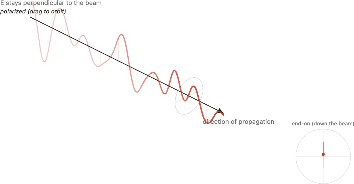
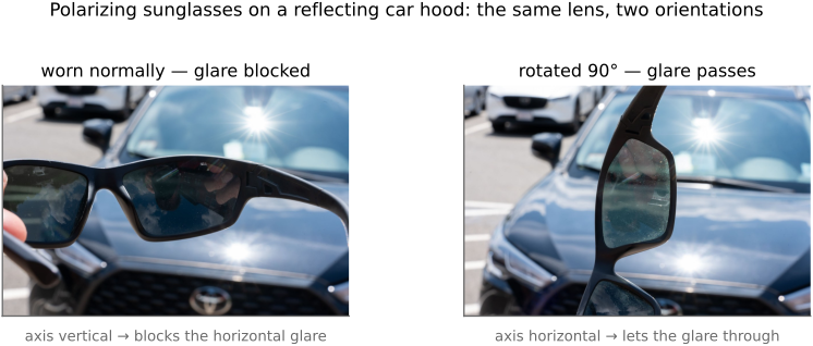
You meet polarization in two everyday places. First, good sunglasses are polarizers. The glare off a road, a lake, or a car hood is light that bounced off a roughly horizontal surface, so it comes out strongly horizontally polarized, especially near Brewster's angle (the why lives in the reflection and BRDF material below). Quality sunglasses are linear polarizers oriented to pass vertical and block horizontal, so they kill that glare specifically, not just dim everything like a plain dark tint. That is the difference between polarized sunglasses and a plain dark tint, and you can see it by rotating the glasses over a reflective surface (Figure 2.1.23). Second, LCD displays emit polarized light: an LCD forms its image by rotating polarization between two crossed polarizers, with the liquid-crystal layer acting as a per-pixel shutter. That is why polarized sunglasses can make some screens go oddly dark, or shift color, when you tilt your head.
How do you make a polarizer in the first place? The everyday kind is Edwin Land's invention. In the late 1920s Land, then a college dropout, worked out how to make a cheap sheet polarizer: line up long needle-shaped crystals (later, iodine-stained polymer chains) in a plastic film by stretching it, so the aligned chains soak up the electric field oscillating along their length and pass only the perpendicular component. He called the material Polaroid and built a company on it (the same Polaroid that went on to make instant film), and that stretched-polymer sheet is still what sits in sunglasses, camera polarizing filters, and the front and back of every LCD. That last case is worth spelling out. A liquid-crystal display is a sandwich of two crossed polarizers with a liquid-crystal layer between them: with no voltage the crystal twists the light's polarization by ninety degrees so it slips through the second polarizer and the pixel is bright, and a voltage untwists it so the second polarizer blocks it and the pixel goes dark. The picture is painted purely by rotating polarization, one pixel at a time, which is also why the light leaving a screen is already polarized, and why tilting polarized sunglasses in front of a laptop can dim it to black.
Polarization is not only a photographer's tool; it is an artist's medium. Austine Wood Comarow (1942–2020) invented Polage, or polarized collage: pictures built from layered cellophane and other birefringent films sandwiched between polarizers. A birefringent film rotates the polarization by an amount that depends on wavelength and thickness, so between crossed polarizers each region glows in a color set by how many films overlap, and the whole image shifts color, or morphs into a different scene, as the viewer or a rotating polarizer turns. Several of her large backlit works are on permanent display at the Museum of Science, Boston. The same physics has been explored as an interface idea in MIT's Polagons, polarization-based color-shifting displays (Polagons PDF).
2.1.7 The color of objects: illumination times reflectance⧉
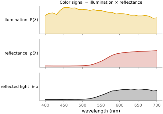
Most objects have no color of its own to emit; they only reflect whatever light falls on them. So the color that reaches your eye is the result of two spectra multiplied together, wavelength by wavelength:
Here $S(\lambda)$ is the illuminant — the spectrum of the light source actually present — and $\rho(\lambda)$ is the surface's spectral reflectance, the fraction of light it sends back at each wavelength. Reflectance is the object's intrinsic, fixed signature: the apple's $\rho(\lambda)$ is high in the reds and low in the greens and blues, whatever the lighting. Illumination is whatever happens to be shining. Their per-wavelength product is what leaves the surface and reaches the eye (Figure 2.1.24). A red apple under white light reflects mostly red; the same apple under pure green light has almost nothing to reflect and looks nearly black, because there is no red illumination for its reflectance to act on.
This multiplicative entanglement is consequential, and it is the first instance of a principle that runs through the whole book.
Much of imaging is multiplicative, not additive. The light reaching the eye is illumination times reflectance; contrast is a ratio of intensities; a shadow darkens a region by a factor, not by subtracting a constant. Because the structure is multiplicative, the natural tools are multiply, divide, and log — not just add. This is why, again and again, we will work with ratios and with logarithmic encodings rather than raw linear values. It is also why white balance is hard: to recover an object's true color we must divide out the unknown illuminant $S(\lambda)$ from the product $C(\lambda)$ — undoing a multiplication we never observed directly. (The additive counterpoint — light from different sources adding — and what it means for choosing an encoding, comes in Color technology.)
Why this multiplicative structure matters so much is a question the rest of the book keeps answering. Our visual system does not care about the illumination for its own sake. It cares about objects, about the reflectance $\rho(\lambda)$ that tells it what a thing is and whether it is food, a face, or a threat. So the brain works hard to discount the illuminant, factoring the product $C(\lambda)=S(\lambda)\,\rho(\lambda)$ back apart to recover the reflectance and hold an object's apparent color and lightness steady as the light changes. That discounting is the perceptual machinery of lightness and color constancy, studied in Human vision and color, and a camera has to imitate it deliberately, which is exactly what white balance does. Much of imaging is this running effort to see past the illumination to the reflectance underneath.
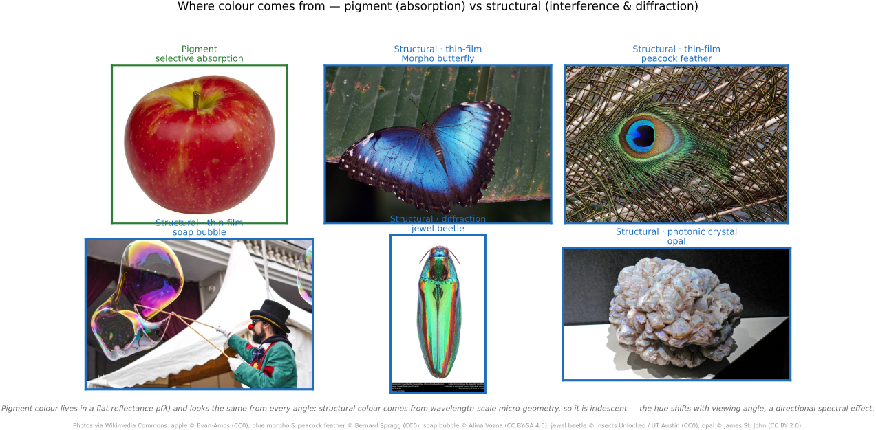
Where color actually comes from. That fixed reflectance $\rho(\lambda)$ — and color in nature more broadly — is produced by only a handful of physical mechanisms that behave very differently in a photograph.
- Pigments — selective absorption. The common case: molecules or crystals whose bound electrons resonate at, and therefore absorb, particular wavelengths (the Lorentz-oscillator picture of Reflection, refraction, and what happens at a surface), leaving the rest to be reflected or transmitted. Chlorophyll's green, the apple's red anthocyanins, paint, dye, ink, the melanin in skin and hair are all pigments. Pigment color looks the same from every direction; it is described by a single reflectance function $\rho(\lambda)$, which is exactly why it photographs as a stable, matte color a camera can capture and a printer can match.
- Structural color: interference and diffraction. Color produced not by any pigment but by micro-geometry on the scale of the wavelength of light, which makes some wavelengths interfere constructively and others cancel. Thin-film interference colors soap bubbles, oil slicks on a wet road, anodized metal, and the brilliant blue of a Morpho butterfly and a peacock feather; diffraction gratings color a CD, holographic foil, and some beetles; photonic crystals color opal. Its hallmark is iridescence: the hue shifts with viewing and lighting angle, because it comes from path-length differences. So unlike a pigment, structural color is strongly directional: a genuinely spectral version of the next section's BRDF, not a single albedo, and the reason it is so hard to reproduce in print, which has no angle to give back.
- Emission. Some things make their own light rather than reflecting it — a glowing filament or the sun (incandescence, fixed by temperature → color temperature, below), a fluorescent dye or a firefly (luminescence). Emission adds light to the scene instead of multiplying the illuminant.
- Scattering. Wavelength-selective redirection by tiny particles. Rayleigh scattering paints the sky blue and the sunset orange (sidebar above), and the very same effect gives blue eyes and some birds their blue without a speck of blue pigment.
For photography the split that matters is pigment versus structural: a pigment is a fixed $\rho(\lambda)$ the camera records and the printer reproduces, whereas a structural color changes as you move, so a single frame freezes only one slice of it and a flat print loses the iridescence entirely (Figure 2.1.25).
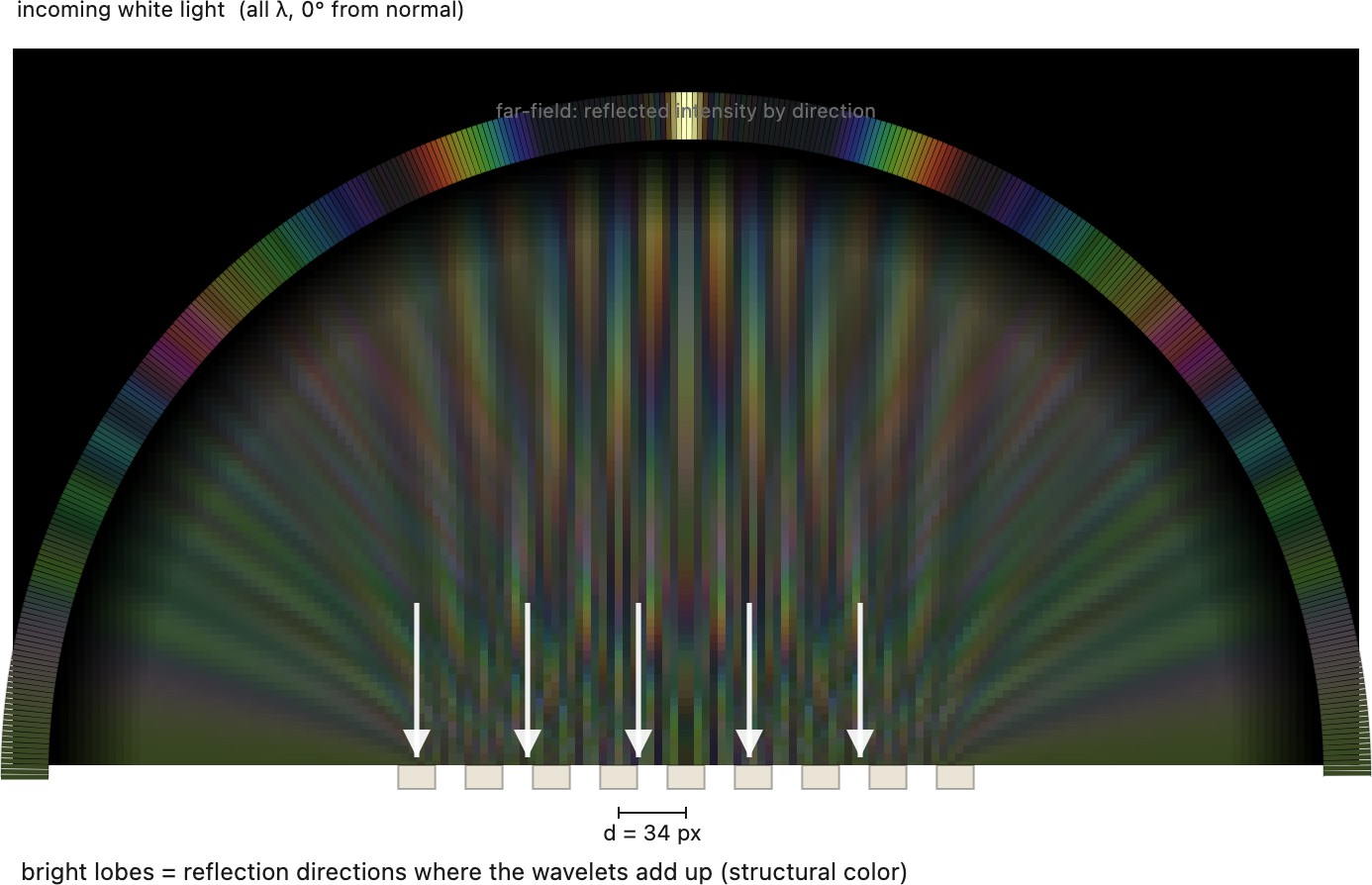
Structural color is nothing more than wavelets interfering, and that is worth seeing directly (Figure 2.1.26). A periodic microstructure re-radiates a wavelet of the incoming light from each of its elements; where those wavelets' paths line up they reinforce into bright lobes and elsewhere they cancel, and because the lobe directions depend on the ratio of wavelength to structure spacing, a fixed viewing direction sees the color shift as either changes. That angle-dependence is the iridescence, and it is why structural color cannot be captured as a single reflectance.
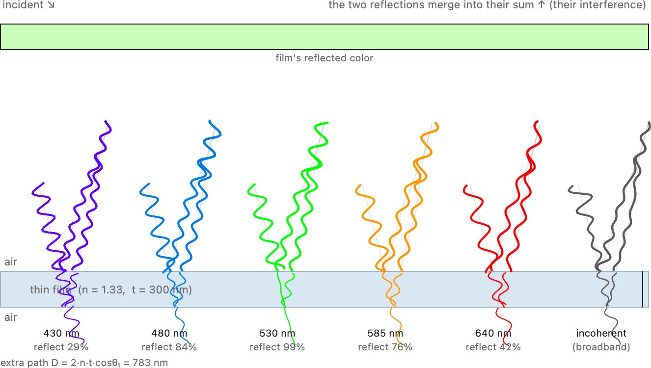
The other common route to structural color is a thin film rather than a periodic array: a single transparent layer, the wall of a soap bubble or the sheen of oil on water, reflects light from both of its surfaces, and those two reflections interfere by an amount set by the film's thickness and the viewing angle (Figure 2.1.27). A given color reflects strongly only when the film's extra path length is a half-integer number of its wavelengths, so as the film thins or you tilt it the reinforced color marches through the spectrum, which is the shifting sheen of a soap bubble about to pop.
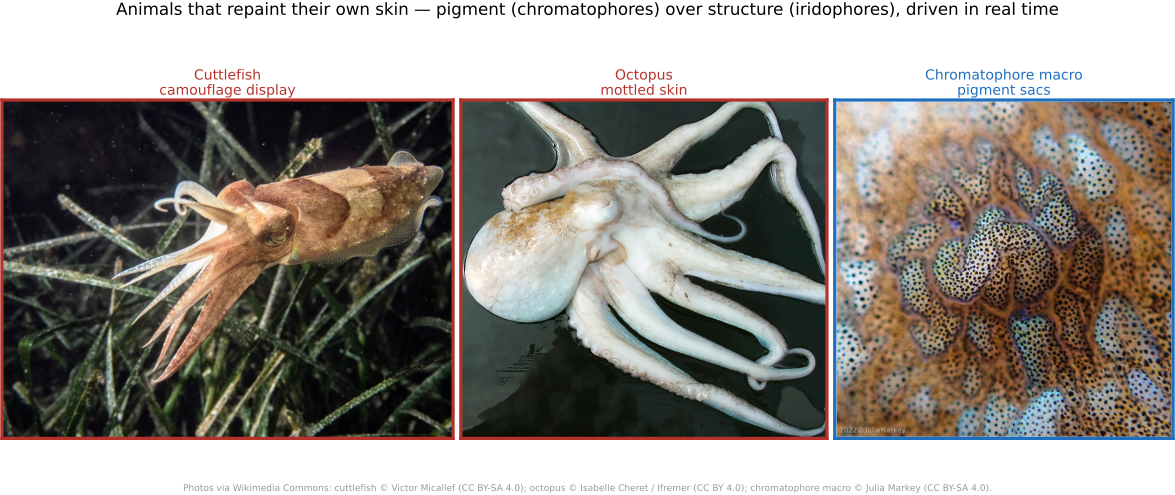
Every mechanism above is fixed once the material is made: a pigment absorbs the same wavelengths today and tomorrow, and a butterfly's scales keep their spacing for life. Cephalopods (octopuses, squid, and cuttlefish) break that assumption. They run two of this section's mechanisms at once and steer both in real time, changing color and pattern in a fraction of a second. The pigment layer is built from chromatophores: microscopic sacs of red, yellow, and brown-black pigment, each ringed by radial muscles wired straight to the brain. Relaxed, a sac shrinks to an invisible dot; when the muscles pull, it stretches into a flat disk and its color spreads across the skin. Because the control is neural rather than chemical, a whole pattern can flash on and vanish in well under a second. Beneath the pigment sits the structural layer: iridophores, stacks of thin protein platelets (the protein is called reflectin) that make blues and greens by the same thin-film interference that colors a Morpho, and leucophores, broadband scatterers that return a neutral white. Some iridophores are tunable, so the animal shifts even its structural color by changing the platelet spacing. Pigment over structure, both under active control, is what lets a cuttlefish settle onto sand and resolve into its exact texture. The twist for a photographer is that most cephalopods are effectively colorblind, with a single visual pigment, yet they still match the colors around them; how they manage it is unsettled, one proposal being that their oddly shaped pupils smear color into depth-of-focus cues the brain can read. Either way, a single frame of a hunting cuttlefish freezes one instant of a display that is really a moving image the animal is painting on itself (Figure 2.1.28).
A caveat on scope: the clean product $C(\lambda) = S(\lambda)\rho(\lambda)$ assumes the surface reflects the same in every direction, the matte or Lambertian case, where a single reflectance number per wavelength suffices. Real surfaces are directional: a shiny apple has a bright highlight that moves as you move. Capturing that direction-dependence requires a richer object than a single $\rho(\lambda)$, and that is the BRDF, next.

2.1.8 The BRDF and the look of materials⧉
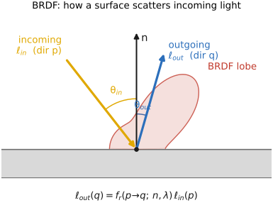
To describe how a real surface reflects, we need a function that knows about directions — both where the light comes from and where the viewer looks from. That function is the bidirectional reflectance distribution function (BRDF). For a point $p$ on a surface with normal $\mathbf{n}$, the BRDF $f_r$ says how much of the light arriving from one direction is re-emitted toward another:
The "bidirectional" in the name is the whole point: the reflected radiance toward a viewer at $q$ depends on both the incoming direction and the outgoing direction (and on wavelength, which is why surfaces are colored). The BRDF is the directional reflectance function of a material: give a renderer the BRDF and it can show you that material under any lighting and from any angle (Figure 2.1.30).
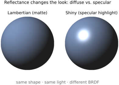
Diffuse versus specular. Two idealized extremes anchor the whole range of materials (Figure 2.1.31). A diffuse, or Lambertian, surface, such as chalk, matte paint, or paper, scatters incoming light into a broad lobe, sending it nearly equally in all directions. Its key, slightly counterintuitive property is that it looks equally bright from every viewpoint: walk around a matte ball and its shading does not change with your position. (What does change its brightness is the angle of the light, which dims as $\cos\theta$ — a fact we make precise in the radiometry section.) A specular, or shiny, surface, such as polished metal, glass, or a wet apple, does the opposite: it concentrates reflection into a tight lobe near the mirror direction, producing a sharp highlight that is view-dependent and slides across the surface as you move. Most real materials are a blend: a diffuse base color plus a specular sheen, which is also how computer-graphics shading models combine them.
A diffuse (Lambertian) surface looks the same brightness and color from every viewing direction — its appearance does not depend on where you stand, only on where the light is. This is an idealization (real surfaces add a view-dependent specular sheen), but it is one a huge amount of computer vision quietly assumes, because it lets a scene point have a single color that can be matched across views. Stereo, multi-view and photometric stereo, optical flow's brightness-constancy, and any "just average the color at this point" reasoning all lean on Lambertian reflectance — and shiny, view-dependent highlights are exactly where they break.
Polarization, again. There is one more thing the BRDF leaves out if we treat reflectance as a single directional number: the light–matter interaction also polarizes the light. As the polarization sidebar above noted, reflection — especially the specular component — partially polarizes what bounces off a surface, with the effect strongest near Brewster's angle. A truly complete account of reflection is therefore polarization-dependent: the BRDF becomes a polarization BRDF, or pBRDF, tracking not just how much light goes where but how its oscillation orientation is reshaped on the way. This is exactly the handle a polarizing filter grabs (Photography 101 — lens filters), and it is what shape-from-polarization and reflection-removal methods exploit to read surface orientation or strip away glare (Advanced).
A BRDF is per-wavelength: the same wavelength goes in and comes out, merely redistributed in direction, so a surface is one BRDF for the reds, another for the blues, and they never talk to each other. Fluorescence violates this. A fluorescent material absorbs short-wavelength light — often ultraviolet — and re-emits it at longer wavelengths, the shift toward red called the Stokes shift. Energy is moved between wavelengths, so the material is no longer described by a scalar BRDF per $\lambda$ but by a bispectral reradiation matrix that maps an input wavelength to an output wavelength. (This is also why a fluorescent surface can appear to reflect more than 100% of the light in its emission band — it is borrowing energy from the ultraviolet you cannot see.) Once you look for it, fluorescence is everywhere: the optical brighteners that make detergent and paper look "whiter than white," highlighter ink, minerals glowing under a UV lamp, green fluorescent protein (GFP) in cell biology, and the hidden security inks in banknotes — and it is the working signal of fluorescence microscopy and forensics.
A BRDF makes one more quiet assumption: that light leaves a surface at the same point it entered. In translucent materials this fails. Light enters, scatters around beneath the surface, and exits somewhere else, so a point-wise BRDF is simply insufficient — what you need is a BSSRDF, the bidirectional surface-scattering reflectance distribution function, which couples a separate entry point to an exit point. Skin, marble, milk, wax, and leaves all do this. It is what gives skin its soft, "lit-from-within" glow and its gently rounded shadow terminator; render skin with a pure BRDF and it looks unmistakably plastic. (Cross-ref: translucency in physically based rendering.)
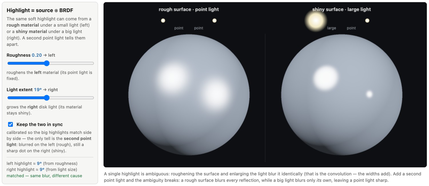
Highlight size: the duality of the BRDF and the light source. Look closely at the bright highlight on a shiny object and ask what sets its size. Two things do, and in exactly the same way. One is the material: a mirror-smooth surface has a needle-thin BRDF lobe and reflects a crisp image of whatever lit it, while a rough surface has a broad lobe that smears that reflection out. The other is the light: a tiny source (a bare bulb, the sun) makes a small hard highlight, and a large source (an overcast sky, a big softbox) makes a large soft one. Change either and the highlight changes the same way, which is the first hint that the two are playing the same role.
They are. The reflected pattern you see is the light source's shape blurred by the BRDF lobe, and "blurred by" is meant literally: it is a convolution over directions. Sweep the incoming light across the sphere of directions and each position contributes the BRDF lobe scaled by how bright the source is there; summing over the whole source convolves the source's angular profile with the lobe. Ramamoorthi and Hanrahan made this precise in their signal-processing framework for reflection (Ramamoorthi & Hanrahan 2001 (reflection as convolution)): reflection off a curved surface is a convolution of the incident lighting with the BRDF, so in the frequency domain (spherical harmonics on the sphere of directions) the reflected signal is the product of the lighting's spectrum and the BRDF's. A sharp, glossy BRDF is a broadband, nearly all-pass filter that lets the lighting's fine detail through, which is why a mirror shows the world in focus; a rough, matte BRDF is a low-pass filter that keeps only the coarse, low-frequency part of the lighting, which is why a diffuse surface shows just a smooth gradient. (It is also why a Lambertian surface can be captured to better than a percent by only about nine numbers: it discards everything above the second frequency band.)
The consequence that matters for looking at pictures is a genuine ambiguity. Because the highlight is a convolution of two widths, you cannot tell from the blob alone which width is which: a small hard source on a slightly rough surface and a large soft source on a shinier surface can produce the very same highlight. The widths combine (roughly in quadrature for bell-shaped lobes), so a given softness can be reached from either side. Recovering the material and the lighting separately from one image is therefore an under-determined inverse problem, exactly the deconvolution Ramamoorthi's framework sets up and bounds.
Managing reflections is half of practical photography. Because the photographer usually cannot change the material, they control the other factor in the convolution: the size and shape of the source. This is the whole craft of lighting shiny things, and it dominates product and portrait work. Photograph jewellery, glassware, a watch, or a car and you are really photographing what the surface reflects, so the studio is built to control that reflection: large softboxes and diffusion panels, light tents, and "painting with light" turn a hard specular pinpoint into a broad, gradient-filled sheen that reveals the object's shape instead of a distracting hotspot. The rule of thumb that a source is softer when it is bigger and closer is just the convolution restated: enlarge the source's angular size and the highlight blurs.
Portraits are the same problem on skin, which carries an oily specular layer over a translucent diffuse one. A small light stamps hard, shiny hotspots on the nose, forehead, and cheekbones; a large soft source close to the subject (a big octabox or umbrella) spreads those into a flattering, gentle sheen. Here the photographer also gets to touch the other half of the convolution, through makeup: matte and mattifying powders roughen the skin's microstructure, broadening the specular lobe until the shine dissolves toward diffuse, while highlighter and gloss do the reverse, narrowing the lobe for a deliberate dewy catchlight. Light modifiers and makeup are the two knobs of one convolution, one acting on the source and the other on the BRDF.
A polarizing filter gives the photographer a third knob, one that removes the reflection at the sensor instead of reshaping it at the source. Light specularly reflected from a dielectric (non-metallic) surface, water, glass, wet leaves, a painted car panel, is partially polarized, most strongly near Brewster's angle (recall Polarization, above). A polarizer rotated to block that axis cuts the glare selectively: it wipes the sheen off foliage and rocks so their true color shows through, sees past the reflection on water and shop windows, and deepens a blue sky by removing the polarized skylight at ninety degrees from the sun. It is the one tool that suppresses a specular highlight without touching the diffuse image underneath, which is why it is the rare lens filter whose effect cannot be reproduced afterward in software. The catch is that it does nothing to reflections off bare metal, which stay unpolarized, so a chrome highlight still has to be managed the slow way, with the size and placement of the source.
Finally, this convolution is also how we read materials. Human observers judge gloss and roughness from the statistics of highlights, their size, sharpness, contrast, and placement, and do so accurately only under realistic, natural illumination; strip the lighting down to a single point and the cues collapse. Fleming, Dror, and Adelson showed that our perception of surface reflectance depends on the rich structure of real-world illumination in just this way (Fleming, Dror & Adelson 2003), part of Adelson's broader program on how we perceive "stuff" rather than things (Adelson 2001 (on seeing stuff)). The size of a highlight, in other words, is not a nuisance to be removed but a signal the visual system uses to tell wet from dry, metal from plastic, and fresh from stale.
2.1.9 Illuminants⧉
We have been treating "white light" as a single thing, but it is not. The light at noon, the light at sunset, the light from a tungsten bulb, and the light from a fluorescent tube all have very different spectra $S(\lambda)$, and since the stimulus reaching the eye is the product $S(\lambda)\rho(\lambda)$, the same scene genuinely sends different colors to the eye under each.
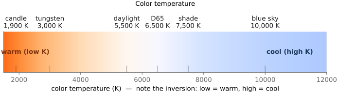
The most useful organizing idea is the blackbody: an ideal hot object whose emitted spectrum is fixed entirely by its temperature. As it heats, it glows first dull red, then orange, yellow, white, and finally bluish, exactly the sequence a heated iron bar runs through. This gives us color temperature, quoted in kelvin (K), as a one-number handle on the color of a light (Figure 2.1.33). The convention is opposite everyday usage: low color temperatures (~3000 K) are warm, orange-ish; high ones (~6500 K and up) are cool, bluish. Standard reference illuminants include D65 (≈6500 K, a model of average daylight, the basis of most color standards), tungsten (≈3200 K, the warm glow of an incandescent bulb), and fluorescent lighting, which is not a smooth blackbody curve but a spiky spectrum with sharp emission lines, which is why fluorescent light renders some colors poorly and gives photos an unpleasant cast.
The lesson, restated, is the one from L2.6: because the stimulus is the spectral product of illuminant and reflectance, a surface's apparent color is never absolute — it shifts with the light. Our visual system silently compensates (a white shirt looks white indoors and out), and a camera must do the same compensation explicitly. That compensation is white balance, and recovering it — dividing out the illuminant — is one of the central problems of Color technology.
2.1.10 Radiometry: radiance, irradiance, exposure, and falloff⧉
Let us be more precise about light *energy: how much light a ray carries and how much of it lands on a sensor. This is radiometry, and getting two of its quantities straight prevents a great deal of confusion later.
Radiance. The fundamental quantity a pixel ultimately measures is radiance $L$: the power flowing along a ray, per unit projected area (the area perpendicular to the ray) and per unit solid angle, so its SI units are watts per square metre per steradian, $\mathrm{W\,m^{-2}\,sr^{-1}}$. Formally $L = \mathrm{d}^2\Phi/(\mathrm{d}A_\perp\,\mathrm{d}\omega)$, the power threading a small patch $\mathrm{d}A_\perp$ inside a small cone of directions $\mathrm{d}\omega$ about the ray (solid angle, measured in steradians (sr), is the 2-D analogue of a plane angle, giving the apparent size of a cone; it is treated in the appendix). Because it depends on both position and direction, radiance is a five-dimensional field: the complete description of the light filling a scene. The essential and surprising property of radiance is that it is conserved along a ray as it travels through empty space: it does not fall off with distance (Figure 2.1.34). A blank white wall does not get dimmer as you step away from it — it only gets smaller in your field of view. Each individual ray from the wall carries the same radiance no matter how far it has traveled; there are simply fewer of those rays landing in each pixel as the wall shrinks. Hold onto this: radiance is distance-invariant, and it is the quantity scenes are made of.
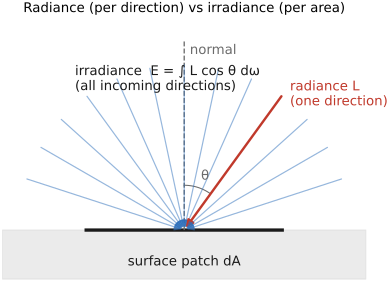
Irradiance. What a sensor actually accumulates is irradiance $E$: the power per unit area arriving on a surface, summed over all the directions that reach it. Because those directions have been integrated away, it carries no per-solid-angle factor: its units are simply watts per square metre, $\mathrm{W\,m^{-2}}$. It is the integral of incoming radiance over the collecting solid angle,
where integrating over the directions $\mathrm{d}\omega$ (in steradians) cancels the $\mathrm{sr}^{-1}$ in radiance, leaving $\mathrm{W\,m^{-2}}$. Unlike radiance, irradiance does depend on the geometry of collection: a wider lens aperture gathers a larger solid angle and so collects more irradiance. That is the radiometric reason a faster lens makes a brighter image.
The cosine law. The $\cos\theta$ inside that integral is not a fudge factor; it is projected area (Figure 2.1.35). Picture a cylindrical beam of light, a shaft of width $w$, striking a surface. If it hits head-on, it illuminates a patch of width $w$. If it hits at an angle $\theta$ from the normal, the same beam spreads over a longer footprint $w/\cos\theta$, so the same power is smeared over more area and the irradiance is thinned by $\cos\theta$. This is Lambert's cosine law: a surface tilted away from the light receives less light per unit area, in proportion to $\cos\theta$. It is why a Lambertian sphere fades smoothly toward its edges.
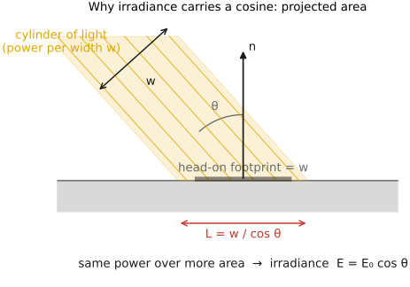
The light a surface receives per unit area is thinned by the cosine of the incidence angle: a beam striking at angle $\theta$ from the normal spreads its power over a footprint $1/\cos\theta$ larger, so irradiance $\propto \cos\theta$ (Lambert's cosine law). This $\cos\theta$ is not a fudge factor — it is projected area — and it reappears everywhere: it is why a matte sphere fades toward its edge ($\mathbf n\!\cdot\!\mathbf l$ shading), why the poles are colder than the equator, why lenses vignette toward the corners ($\cos^4$), and it sits inside every radiometric integral over the hemisphere.
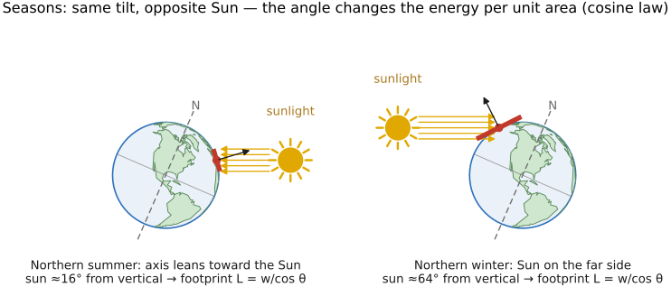
The cosine law explains the seasons, and it is not about distance from the sun (Earth is actually slightly closer to the sun in the northern winter). The Earth's axis is tilted 23.5°. In summer the noon sun stands high and its rays strike the ground near vertically — concentrated, full strength. In winter the noon sun is low and the same rays arrive at a grazing angle, spreading the same power over a larger patch of ground — by the cosine law, roughly half the energy per unit area. Summer is warm because sunlight is concentrated, not because we are nearer the sun (Figure 2.1.36).
Radiometric versus photometric units. Everything above is radiometric, meaning raw energy measured in watts. But the eye does not weigh all wavelengths equally, and the photographic and display worlds quote a parallel set of photometric units that fold in the eye's spectral sensitivity, the luminous-efficiency curve $V(\lambda)$. Weight a radiometric quantity by $V(\lambda)$ and integrate over wavelength and you get its photometric twin: radiant flux in watts becomes luminous flux in lumens (lm); irradiance in W/m² becomes illuminance in lux (lm/m², what an incident light meter reads); radiance in W/m²/sr becomes luminance in cd/m², the "nit," and intensity in W/sr becomes luminous intensity in candela (cd), which is the SI base unit (roughly the output of one candle). The chain is consistent: $\text{cd/m}^2 = \text{lm}/(\text{m}^2\cdot\text{sr})$. Luminance, cd/m², is the one to remember: it is the perceptual "brightness" of a patch, and it is the unit displays and HDR are specified in and the axis the photopic/scotopic perception scale lives on. For a sense of scale, a typical monitor runs ~100–300 cd/m², an HDR display reaches 1000+, and white paper in direct sunlight is around $10^4$ cd/m².
Luminance in photons. Because light is quantized, any of these units can be restated as a rate of photons, which is often the more physical way to think about faint light and about sensor and retinal noise (where the discrete arrivals are the signal). At the photopic peak, $555\,\text{nm}$, where $1\,\text{W}$ of radiant power equals $683\,\text{lm}$, one photon carries $E=hc/\lambda\approx 3.6\times10^{-19}\,\text{J}$, so $1\,\text{lm}$ is about $4.1\times10^{15}$ photons per second and a luminance of $L$ (cd/m²) is a photon radiance of roughly
(Broadband daylight is spectrally less efficient, around $200\,\text{lm/W}$, so a real scene carries a few times more photons than this for the same luminance.) The spread across everyday scenes is enormous, about fifteen orders of magnitude:
| Condition | Luminance (cd/m²) | Photon radiance (555 nm, photons·s⁻¹·m⁻²·sr⁻¹) |
|---|---|---|
| The sun's disc | ~$1.6\times10^{9}$ | ~$7\times10^{24}$ |
| White surface in bright sunlight | ~$10^{4}$ | ~$4\times10^{19}$ |
| Overcast sky | ~$10^{3}$ | ~$4\times10^{18}$ |
| Well-lit room / white paper indoors | ~$10^{2}$ | ~$4\times10^{17}$ |
| Twilight | ~$1$ | ~$4\times10^{15}$ |
| Full-moon landscape | ~$10^{-2}$ | ~$4\times10^{13}$ |
| Starlit (moonless) landscape | ~$10^{-3}$ | ~$4\times10^{12}$ |
| Absolute visual threshold | ~$10^{-6}$ | ~$4\times10^{9}$ |
These photon-radiance numbers are per unit area and solid angle; turned into what a single photoreceptor actually catches (photons per cone or rod per second), once the eye's pupil and the cone's collecting area are folded in, they become the counts in Human Vision (Light adaptation), and the same photon bookkeeping drives sensor shot noise in Noise, signal-to-noise ratio and dynamic range.
The sun versus what it lights: about 46,000×. Radiance lets us pin down a startling number: how much brighter is the sun than the surfaces it illuminates? Take a perfectly white (albedo 1) matte surface facing the sun. It absorbs nothing and re-radiates all the light it receives, spreading that power evenly over the hemisphere above it, so its radiance is $L_{\text{surf}} = E_\odot/\pi$, where $E_\odot$ is the sun's irradiance on it. But the sun delivers that irradiance from a tiny disc: overhead, $E_\odot = L_\odot\,\Omega_\odot$, where $L_\odot$ is the sun's own radiance and $\Omega_\odot \approx 6.8\times10^{-5}$ sr is its solid angle (the sun is only about half a degree wide). Dividing, the sun's disc outshines the white surface it lights by
roughly 15.5 stops (a stop is one doubling of light, the photographer's base-2 unit of brightness ratio, $\text{stops}=\log_2$ of the ratio; it is formalized with exposure value in Exposure). The picture is simple: the surface takes the sun's power, concentrated into a $6.8\times10^{-5}$ sr cone, and smears it across the full $\pi$ sr of a projected hemisphere. Radiance is power per unit solid angle, so the ratio of those two solid angles is the ratio of brightnesses. This single number explains a great deal: why no ordinary single exposure can hold both the sun and the scene it lights (the reason for high-dynamic-range imaging), why the sun is dangerous to look at while the wall it lights is not, and why lens flare matters at all. A stray internal reflection carrying even a ten-thousandth of the sun's radiance still rivals the properly-exposed scene, which is exactly why the sun's ghosts are so visible (the flare traced in the OPTICS part, the figure).
Falloff. A point source, such as a bare bulb or a star, does fall off as the inverse square of distance, $E \propto 1/r^2$: its light spreads over a sphere whose area grows as $r^2$, so the irradiance on anything it lights drops as $1/r^2$. This should be familiar: a light is brighter up close. But the radiance carried by one ray itself is distance-invariant — the wall does not dim. How can both be true? The resolution is that they describe different things: $1/r^2$ governs the irradiance a point source delivers, while distance-invariance governs the radiance of an extended surface as seen along a ray (Figure 2.1.37). The surface's radiance stays constant; what shrinks is its angular size, not its brightness. Essentially radiance describes the invariant integrand but the square distance falloff describes the integral over the shrinking solid angle.
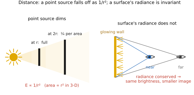
One point closes the loop. A true point source is an idealization; nothing is infinitely small. Every real source (a bulb, the sun, a softbox) is a finite extended surface with its own conserved radiance, and what it delivers to a lit point is fixed by the solid angle it subtends there, exactly the bookkeeping of the sun-versus-wall count above. Step away and that solid angle shrinks as $1/r^2$ (its angular width falls as $1/r$ in each of two dimensions), so the irradiance it delivers falls as $1/r^2$ as well. A point source is simply the limit of such a finite source shrunk toward zero angular size while its total emitted power is held fixed, and its inverse-square law is that same solid-angle collapse carried to the limit. So the two falloff behaviors are really one story: the radiance carried along a ray never changes, but the solid angle a source occupies collapses with distance, and $1/r^2$ is the rate of that collapse.
This radiometric bookkeeping is what later chapters build on. Recovering the true scene radiance from one or several photographs is the goal of high dynamic range (HDR) imaging; deliberately controlling the illumination to learn about a scene is computational illumination. (One more piece of falloff — the gentle $\cos^4\theta$ dimming toward the corners of a frame, or natural vignetting — is deferred to the Sensors chapter, where a finite aperture and a real pixel make it meaningful.)
2.1.11 Global illumination⧉
We have been treating the light on a surface as arriving straight from the illuminant. But in a real scene most surfaces are also lit indirectly, by light that has already bounced off other surfaces. Light rarely bounces only once: it ricochets between the walls, floor, ceiling, and the objects in the scene many times, so the light arriving at any point is the source plus the light reflected off everything else around it. Accounting for all these bounces is global illumination, the foundation of physically based rendering Pharr, Jakob & Humphreys, Physically Based Rendering. A consequence is color bleeding: a red wall casts a faint red tint onto a white floor beside it (Figure 2.1.38). Light striking a surface already carries the colors of its surroundings.
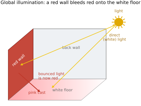
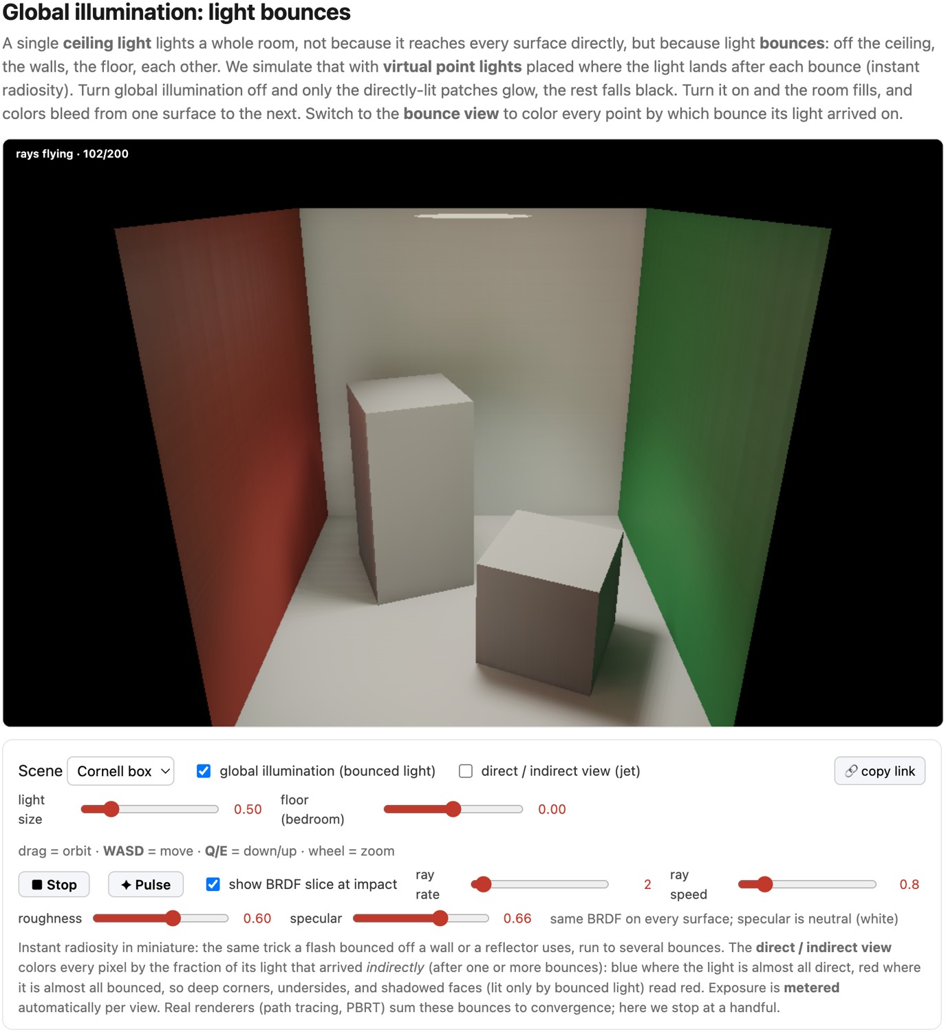
Photographers lean on this constantly. Much of the craft of lighting is the deliberate use of indirect light: instead of aiming a hard source straight at the subject, you send it by way of a large surface that becomes the real, soft source. A reflector, a white or metallic panel held to one side, catches the sun and throws it back to open up a shadow (Figure 3.6.4). Bouncing a flash off a wall or ceiling turns that whole surface into the light (Figure 3.6.3). A studio umbrella or softbox does the same by design (Figure 3.6.5). In each case the light reaching the face has bounced once on the way, which is global illumination working for the photographer rather than merely complicating the render.
2.1.12 Wave effects, diffraction, and the diffraction limit⧉
We end where we began, with the wave picture, because it imposes a limit on every imaging system ever made. When light passes through a small aperture or skims a sharp edge, it does not continue in perfectly straight rays: it diffracts, bending and spreading out. And, counterintuitively, the smaller the aperture, the more the light spreads (Figure 2.1.40). A wide opening lets the wavefront through almost undisturbed; a narrow one forces it to fan out, through an angle of roughly $\theta \approx \lambda / D$ for an aperture of diameter $D$.
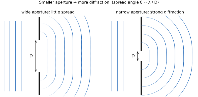
Where does that spreading come from? It is purely a property of waves, and we can watch it happen by solving the wave equation directly. Send a flat wavefront at an opaque barrier with a single slit and let the wave evolve in time: in front of the slit the wavefronts stay flat, but the moment they pass through, they bow into expanding circular arcs and fan outward (Figure 2.1.41). Narrow the slit relative to the wavelength and the fan opens wider — exactly the $\theta \approx \lambda / D$ behavior, now as an emergent consequence of the wave dynamics rather than a rule asserted.
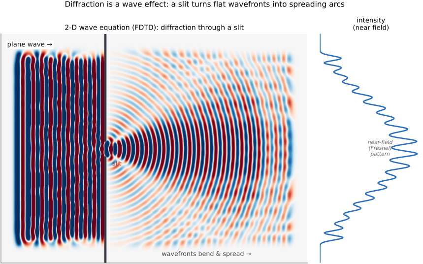
The Airy disk. The consequence for imaging is unavoidable: a finite aperture cannot focus light to a perfect point. Even a flawless, aberration-free lens images a single distant point not as a point but as a small bright blur, the Airy disk, surrounded by faint rings, whose angular radius is
giving a blur-spot diameter on the order of $2.44\,\lambda N$, where $N = f/D$ is the lens's f-number (Figure 2.1.42). The Airy disk is the diffraction-limited point-spread function: the smallest spot any lens of that aperture can produce, set by wavelength and f-number alone.
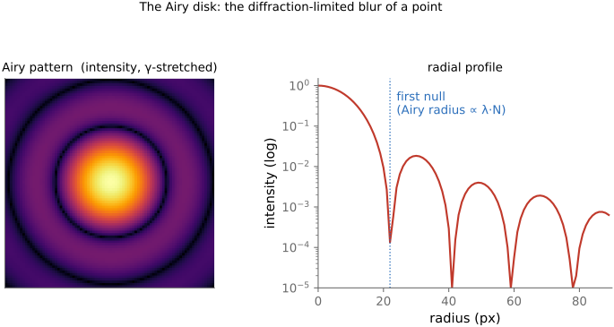
The diffraction limit. Because two nearby point sources blur into two overlapping Airy disks, there is a finest detail a lens can resolve — the diffraction limit. By the Rayleigh criterion, two points are just resolvable when the center of one Airy disk falls on the first dark ring of the other, again at $\theta \approx 1.22\,\lambda/D$. The headline is that a larger aperture diffracts less and resolves finer detail.
Counter to ray-optics intuition, a smaller aperture spreads light more: the diffraction blur (the Airy disk) grows as $\sim\!\lambda N$ with f-number, so stopping down past a point softens the image instead of sharpening it. The flip side is the rule behind every instrument that must resolve fine detail — only a large aperture can diffract little and resolve finely — which is exactly why microscopes and telescopes are built around large lenses and mirrors, and why a phone camera's tiny aperture hits a hard resolution wall it cannot pass. It is the optical cousin of "you can't sample your way past Nyquist."
This produces the photographer's sweet spot. Open the aperture wide and aberrations (the imperfections of real glass, deferred to the Optics part) dominate, softening the image. Stop the aperture far down and diffraction dominates, softening it again. Somewhere in between, typically a couple of stops down from wide open, the two effects are jointly minimized and the lens is at its sharpest. "Stopping down too far softens the image" is not a defect of cheap lenses; it is physics, and the trade-off is made quantitative with the modulation transfer function in the Optics part.
Recap: big lessons of this chapter
We will lean almost entirely on ray (geometric) optics, because nearly every source and interaction we meet is incoherent, and incoherent imaging is linear in intensity. The one piece of the wave picture we hold onto is that the physical color of light is its spectral distribution, the energy it carries at each wavelength. The exceptions to the ray picture are narrow: light squeezed through a small hole (diffraction), a thin film (interference), or a fine structure (structural color), and even structural color we can usually fold into absorption and go on treating the light as rays. Ray optics and incoherent imaging are linear, with one standing catch: the quantities are always positive, so we can add light but never subtract it. Coherent light and full wave optics, where amplitudes add and can cancel, come back only for the advanced topics of metalenses, lensless cameras, and holography, and the particle picture we keep mostly for modeling noise. So most of the time we will picture light as a set of rays traveling in straight lines through homogeneous media, each carrying a radiance that is itself a distribution over wavelength. With that, we have followed light from its source, off a surface, and to the edge of the camera; the chapters that follow take up how eye and camera turn that light into color and into an image.
Light, and the physical color it carries, is described by a spectral distribution: the power it carries at each wavelength, a function $S(\lambda)$. One wavelength is a single pure color; real light is a weighted mix of all of them. Everything downstream (how a prism fans light out, how a surface reflects it, how a sensor or an eye turns it into a perceived color) starts from this per-wavelength power.
What we call brightness or intensity is the power of the electromagnetic field, a quadratic quantity of the field. We never record the field itself, only its time-averaged square, so brightness is always non-negative and blind to the field's sign and phase. And because it is quadratic rather than linear in the field, two light contributions do not simply add in brightness: squaring their summed fields leaves a cross term, and whether that term survives or averages away is what coherence decides.
Coherence decides which quantity of light is linear. Coherent light superposes amplitudes, so its cross terms survive as interference; incoherent light superposes intensities, because the random phases average the cross terms away. No source is fully one or the other, only more or less coherent at a given scale of time and space. Ray optics is what emerges in the incoherent, short-wavelength corner of this space: interference washes out, intensities add along paths, and light travels as independent rays of energy. Most photography involves incoherent light, which means that it is linear in intensity.
At a boundary between two media, light bends by $n_1\sin\theta_1 = n_2\sin\theta_2$ — toward the normal entering a denser medium, away from it on the way out. This single rule is the seed of all lens optics: every focal length, every ray trace, the thin-lens equation, and every aberration is Snell's law applied at curved glass surfaces. Pair it with the fact that the index $n$ depends on wavelength (the next lesson) and you also get dispersion. Almost everything optical in this book traces back to it.
The refractive index is not a constant: $n(\lambda)$ depends on wavelength — in ordinary glass it rises toward the blue, so blue bends more than red. Because of this you cannot route every wavelength the same way with a single refraction: a prism fans white light into a spectrum, a raindrop makes a rainbow, and a simple lens focuses blue and red at slightly different distances — chromatic aberration. Much of the craft of lens design (combining crown and flint glass into achromatic and apochromatic groups) exists to fight this one fact. Dispersion is not a defect of cheap glass; it is built into how matter and light interact.
Much of imaging is multiplicative, not additive. The light reaching the eye is illumination times reflectance; contrast is a ratio of intensities; a shadow darkens a region by a factor, not by subtracting a constant. Because the structure is multiplicative, the natural tools are multiply, divide, and log — not just add. This is why, again and again, we will work with ratios and with logarithmic encodings rather than raw linear values. It is also why white balance is hard: to recover an object's true color we must divide out the unknown illuminant $S(\lambda)$ from the product $C(\lambda)$ — undoing a multiplication we never observed directly. (The additive counterpoint — light from different sources adding — and what it means for choosing an encoding, comes in Color technology.)
A diffuse (Lambertian) surface looks the same brightness and color from every viewing direction — its appearance does not depend on where you stand, only on where the light is. This is an idealization (real surfaces add a view-dependent specular sheen), but it is one a huge amount of computer vision quietly assumes, because it lets a scene point have a single color that can be matched across views. Stereo, multi-view and photometric stereo, optical flow's brightness-constancy, and any "just average the color at this point" reasoning all lean on Lambertian reflectance — and shiny, view-dependent highlights are exactly where they break.
The light a surface receives per unit area is thinned by the cosine of the incidence angle: a beam striking at angle $\theta$ from the normal spreads its power over a footprint $1/\cos\theta$ larger, so irradiance $\propto \cos\theta$ (Lambert's cosine law). This $\cos\theta$ is not a fudge factor — it is projected area — and it reappears everywhere: it is why a matte sphere fades toward its edge ($\mathbf n\!\cdot\!\mathbf l$ shading), why the poles are colder than the equator, why lenses vignette toward the corners ($\cos^4$), and it sits inside every radiometric integral over the hemisphere.
Counter to ray-optics intuition, a smaller aperture spreads light more: the diffraction blur (the Airy disk) grows as $\sim\!\lambda N$ with f-number, so stopping down past a point softens the image instead of sharpening it. The flip side is the rule behind every instrument that must resolve fine detail — only a large aperture can diffract little and resolve finely — which is exactly why microscopes and telescopes are built around large lenses and mirrors, and why a phone camera's tiny aperture hits a hard resolution wall it cannot pass. It is the optical cousin of "you can't sample your way past Nyquist."