2.17 Displays⧉
A photograph is not finished when it is captured, or even when it is developed. It is finished when someone looks at it, and where they look changes what they see. The same file is a different picture on a phone held at arm's length, on a laptop, on a television across a living room, and thrown by a projector onto a wall. This chapter is about the last link in the chain, the display, and about why its characteristics feed back into every processing decision upstream.
2.17.1 The range of displays⧉
Displays span a wide range of sizes, technologies, and viewing conditions:
- Phone screens. Small, held close (about 30 cm), and viewed everywhere from a dark room to direct sunlight. They are dense (often 400 to 500 pixels per inch), bright enough to fight glare, and increasingly OLED with per-pixel emission and true blacks. Most photographs taken today are also watched on a phone.
- Laptop and desktop monitors. Larger, viewed at roughly half a meter to a meter, and the workhorse for editing. A good editing monitor is calibrated, covers a known color space (sRGB, or wide-gamut Display P3 or Adobe RGB), and is viewed in controlled light.
- Televisions. Large, viewed from several meters, and the home of video. Modern TVs push high brightness and HDR (HLG and PQ, from the video chapter), wide gamut (Rec. 2020), and high refresh rates, and they often apply their own processing (motion interpolation, local dimming, sharpening) that the photographer did not ask for.
- Projectors. Large and cheap per unit area, but dim, low in contrast (ambient light lifts the blacks), and dependent on the screen and the room. Cinema projection is a controlled version of the same problem.
- Print. The oldest display of all, reflective rather than emissive, with a contrast set by the paper and the room light. Print is covered with tone reproduction and gamut mapping elsewhere; it is worth remembering as the display with the narrowest dynamic range.
Beyond these sit the near-eye displays of virtual and augmented reality, which are a subject of their own; this chapter points forward to the Integral and immersive imaging part for headsets, light-field displays, and retinal projection.
Their dynamic ranges look very different on a spec sheet than in a living room. The contrast a display can reach in ideal conditions (a dark, calibrated room) is often enormous, but in typical conditions ambient light reflecting off the screen sets a gray floor under the blacks and collapses the usable range to a few hundred to a few thousand to one. The table gives rough orders of magnitude for the on-screen contrast ratio (brightest reproducible over darkest):
| Display | Dynamic range, ideal (dark, calibrated) | Dynamic range, typical (ambient light) |
|---|---|---|
| Reflective print | ~100:1 glossy, ~50:1 matte | ~30–50:1 (room light and surface glare) |
| Standard LCD (IPS / VA) | ~1,000:1 (IPS) to ~4,000:1 (VA) | ~100–200:1 (reflections lift the black) |
| Mini-LED / local-dimming LCD | ~10,000:1 to ~100,000:1 | ~1,000:1 |
| OLED (TV or phone) | effectively ~1,000,000:1 (true black) | ~1,000–5,000:1 (surface reflections dominate) |
| Home projector | ~1,000–2,000:1 (dark room) | ~50:1 (ambient washes out the blacks) |
| Cinema (DCI projection) | ~2,000:1 (dark theater) | (viewing room is kept dark by design) |
The lesson is that a display's black level, not its peak brightness, is what ambient light steals first, so real-world dynamic range is dominated by the viewing environment as much as by the panel. It is why OLED's spectacular contrast largely evaporates on a sunlit phone, why print is the narrowest display of all, and why the same picture needs a different tone curve for a dark theater than for a bright office. This is the display-side reason tone mapping and the viewing-condition adjustments below both exist.
2.17.2 Display technology⧉
There are two ways to put an image in front of the eye: a screen you look at, and a projector whose reflection you look at. A screen produces or modulates light right at the image plane. A projector modulates a small, bright beam and a lens throws it onto a separate white screen, so what you see is reflected light. Projectors buy size cheaply, a wall-sized image from a shoebox, but they pay for it in brightness and contrast: the throw spreads a fixed lumen output over a large area, and any ambient light in the room also lands on the screen and lifts the blacks, so a projected black is only as dark as the room. Screens keep the light concentrated and shrug off ambient light far better, which is why phones and televisions are screens while cinemas are projectors.
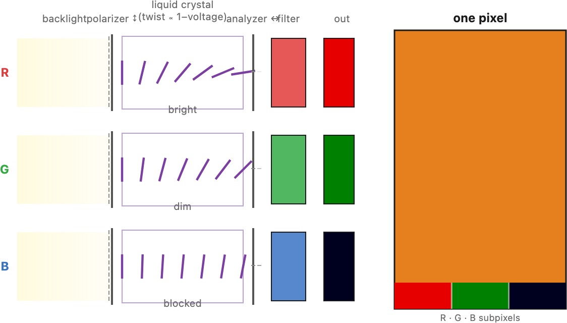
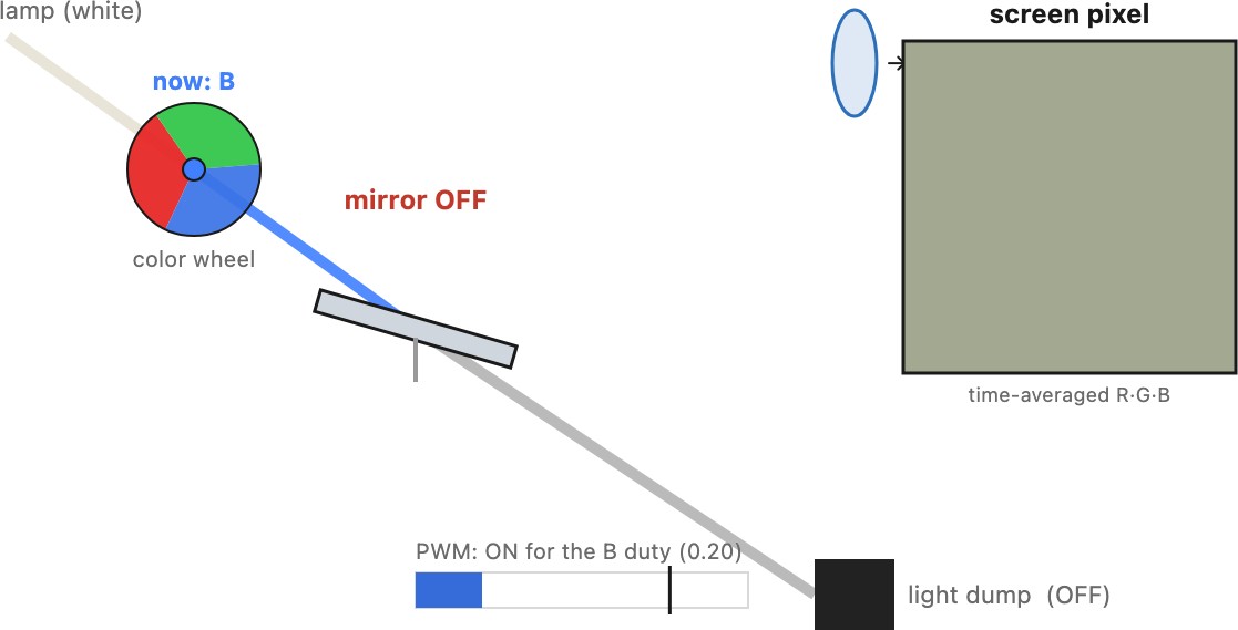
Within both, the pixel is built one of three ways. Emissive displays (OLED, microLED, the old CRT and plasma) make light at every pixel, so each pixel can go fully dark on its own, giving true blacks, high contrast, and a wide viewing angle. Transmissive displays, the LCD, put a fixed white backlight behind a grid of per-pixel valves that pass or block light through red, green, and blue filters (Figure 2.17.1). The valve is a twisted liquid crystal that rotates the light's polarization by an amount the voltage sets, sitting between two crossed polarizers, so a subpixel is a light gate, not a light source. LCDs are cheap, bright, and everywhere, but the valve leaks a little, so their blacks are never quite black and their contrast trails OLED. Reflective modulators steer reflected light instead: the printed page (the next section), electronic ink, and the digital micromirror device (DMD) at the heart of DLP projectors, an array of tiny mirrors that each tilt to throw light either into the lens or into a black light dump, using pulse-width modulation for gray levels and a spinning color wheel for color (Figure 2.17.2). Most projectors are built on one of DMD (DLP), LCD, or LCoS (liquid crystal on silicon, a reflective LCD), a choice that trades contrast, cost, and the "rainbow" flashes of sequential color.
2.17.3 HDR displays and dual modulation⧉
A high-dynamic-range display has to do two contradictory things at once: reach a high peak brightness (hundreds to a few thousand nits, so a specular highlight or the sun can actually be bright) and, in the same frame, hold a deep black (so a night sky stays black), and hold them side by side. The ratio between them is the simultaneous contrast, and HDR wants it in the millions. An emissive panel gets this almost for free: OLED and microLED make light per pixel, so a bright pixel can sit next to a fully-off one and the contrast is limited only by how bright each pixel can be driven. The hard case is the LCD, because it does not make light; it only valves a backlight, and the valve leaks. Put a single uniform backlight behind it and the blacks are gray no matter how good the panel, so a naïve LCD cannot be HDR.
The trick that rescues the LCD is dual modulation (also double modulation or local dimming): modulate the light twice, in two stacked layers, and let the two modulations multiply (Seetzen et al. 2004 (HDR display)). Behind the full-resolution LCD panel sits a second, much coarser modulator, an array of independently dimmable LEDs, hundreds to thousands of local-dimming zones. The backlight layer paints a blurry, low-resolution version of the image's brightness, dimming its LEDs to near zero everywhere the picture is dark and driving them hard where it is bright; the LCD layer then paints the fine detail on top. Because light passes through both, the on-screen luminance is the product of the two: a pixel that is dark needs only each layer to be modestly dark, and the achievable contrast is the backlight's contrast times the panel's. Two leaky modulators in series, each maybe a few hundred to one, multiply to the hundreds of thousands or millions to one that HDR needs. It is the display-side echo of a theme from imaging: when one modulator is not enough, cascade two.
The catch is resolution mismatch. The backlight has far fewer zones than the panel has pixels, so it cannot follow fine structure. A small bright object on a black field, a star, a candle, white text on black, forces its whole backlight zone on, and the LCD cannot fully valve the leakage back down, so a faint halo or bloom spreads around the bright feature, and shadow detail sitting in a lit zone is crushed. More zones shrink the halo, which is the entire pitch of mini-LED backlights (thousands of tiny zones) over the older edge-lit handful; the limit, one zone per pixel, is just an emissive display again. So the zone count is a cost-versus-blooming dial, and driving it well is a real optimization: the display solves for the backlight pattern and then compensates the LCD values for the light it will actually receive, a small inverse problem run every frame. This is the technology behind the mini-LED / local-dimming row in the dynamic-range table below, and the reason HDR content also needs the PQ and HLG encodings and the tone mapping of the video and tone-reproduction chapters: a display that can span that range is only useful if the signal carries the range and is fitted to it.
2.17.4 The film movie projector⧉
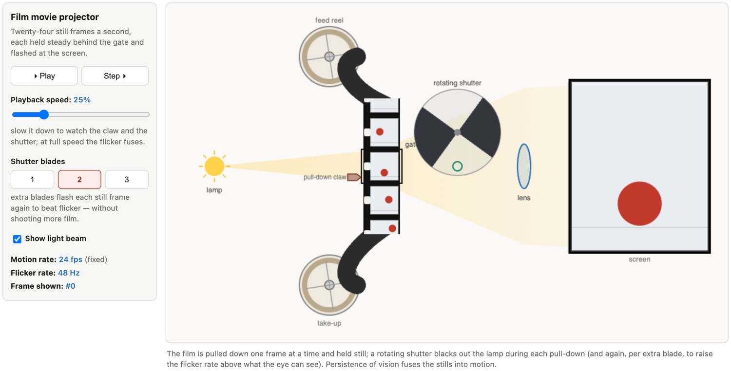
The film movie projector deserves its own look, because it solves a problem that sounds impossible: show two dozen still pictures a second, each held rock-steady long enough to be seen, on a single strip of film that must keep moving. If the film simply slid past the lamp continuously, every frame would smear into a streak. The answer, shared with the movie camera that shot the film, is intermittent motion: the film is jerked forward one frame, held dead still while it is projected, then jerked forward again, twenty-four times a second.
The mechanism that does this is a small marvel (Figure 2.17.3). A pull-down claw darts into the film's sprocket holes, drags one frame down into the gate (the aperture in front of the lamp), then withdraws and lets the film sit motionless while that frame is projected. Above and below the gate the film is fed and taken up by continuously turning sprocket rollers, so the strip is moving smoothly at the reels but in stop-start jerks at the gate; the mismatch is absorbed by two slack loops of film (the Latham loops) that let the intermittent claw yank its frame without fighting the steady pull of the reels or tearing the perforations. In many projectors the continuous-to-intermittent conversion is done by a Maltese-cross (Geneva) movement, a pin on a spinning wheel that advances a slotted cross one quarter-turn per revolution and locks it still the rest of the time.
The last piece is the rotating shutter, and it hides the motion. A bladed disc spins in front of the lamp and blocks the light during each pull-down, so the audience never sees the film move, only a succession of still frames separated by darkness. Here is the subtlety: at twenty-four blackouts a second the screen would flicker unbearably. So the shutter carries two or three blades and interrupts each already-still frame a second or third time, flashing it 48 or 72 times a second. No new pictures are shown, twenty-four unique frames remain, but the flicker rate is pushed above the eye's flicker-fusion threshold, so the image reads as steady. The projector thus runs two clocks at once, a 24 Hz motion rate and a 48–72 Hz flicker rate, decoupled precisely because raising the frame rate would waste film while raising only the flash rate is free. Persistence of vision and apparent motion (the phi phenomenon) then fuse the still frames into continuous movement, and an optical soundtrack, read by a lamp and photocell a little ahead of the gate where the film runs smoothly, plays in sync. The whole device is a display: the playback twin of the camera's intermittent transport, turning a ribbon of stills back into moving pictures.
2.17.5 Printing⧉
A print is the oldest display and the only reflective one most people own: it makes no light of its own but modulates the light of the room, so its brightness and contrast are set by the paper and the ambient light. It is also the hardest color problem in the book, for three reasons that compound.
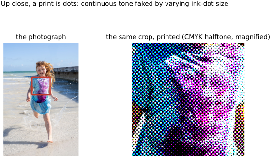
First, ink is binary at the drop. An inkjet head fires tiny droplets of a few fixed inks, and at any spot there is either a dot of ink or bare paper, with no "half-gray ink" in between. Continuous tone is faked by halftoning: laying down dots whose size or spacing varies so that, averaged by the eye at a normal distance, a field of small dots reads as light gray and a field of large ones as dark (Figure 2.17.4). Up close the illusion breaks and the dot structure appears, which is the signature of a print. The classic screen prints the inks at different angles so their dots interleave into a rosette rather than clashing into moiré.
Second, ink mixes subtractively and imperfectly. The process inks are cyan, magenta, and yellow, each subtracting a band (Measuring and encoding color), plus a separate black (K) because stacking C, M, and Y never makes a true dense black and mixing three inks for every dark pixel wastes ink and soaks the paper. Real inks are not the ideal blockers of the theory: their absorption bands are broad and overlapping, so the reachable gamut is small and skewed, dot gain (ink spreading on paper) darkens the midtones, and the paper's own tint shifts the whites. Getting a predictable color out of this requires a measured printer profile and heavy gamut mapping (the color-management section below), which is why a print rarely matches the screen it was proofed on without care.
Third, a print is a showcase for metamerism. The inks are mixed to match target colors under a particular viewing light, but a matched color is really a match between two different spectra that only agree under that one light (illuminant metamerism, Human Vision). So two prints, or a print and the original, that match in the shop can visibly diverge under a different bulb. Print shops therefore specify a standard viewing light (often D50), and "does it match?" is never a question you can answer without first naming the light.
2.17.6 Why the display characteristics matter⧉
Five characteristics of a display change both the experience of a picture and the processing that should be applied to it:
- Size and viewing distance. What matters to the eye is the angle a picture subtends, which is size divided by distance, not size alone. A phone at 30 cm and a television at 3 m can fill the same visual angle. This sets how much resolution is useful (past the eye's roughly one arc-minute acuity, more pixels are invisible) and how large detail, noise, and artifacts appear. A little noise invisible on a phone can be obvious on a wall.
- Resolution. The pixel density, together with the viewing distance, decides whether the display resolves the image or the image out-resolves the display. Downscaling for a small screen hides noise and needs care (prefilter before you downsample, from the sampling chapter); upscaling for a large screen needs interpolation or super-resolution.
- Dynamic range. A print holds a contrast of a few hundred to one, a standard screen a bit more, an HDR display far more. A picture graded for one will look wrong on another: an HDR image shown on a standard screen clips, and a standard image stretched onto an HDR screen looks harsh. Tone mapping exists precisely to fit a scene's range to the display's, and the target range is a property of the display.
- Gamut. The set of colors a display can produce, its primaries and white point, sets which colors survive. Sending Display P3 content to an sRGB screen desaturates it; sending sRGB numbers to a wide-gamut screen without tagging oversaturates it. This is the color-management discipline of the color chapter, and it is the display end of it.
- Viewing environment. Ambient light, the color of the surround, and the viewer's adaptation all change appearance. A phone in sunlight needs more brightness and contrast; a movie in a dark room can use a gentler gamma. Cameras and displays both sense the ambient light (the ambient-light sensor of the Cameras chapter) and adapt.
The throughline is that the display is not a neutral window. It has a size, a resolution, a dynamic range, a gamut, and a viewing environment, and a picture is only as good as the match between how it was prepared and where it is shown. This is why the pipeline that produces an image has to know its destination, and it is the display-side counterpart of the discipline the rest of the book keeps returning to: never touch a pixel without knowing what it means, and never show one without knowing where it will be seen.
2.17.7 Distance, resolution and acuity⧉
A display has "enough" resolution when its pixels are too fine for the eye to pick out individually, and whether that holds depends as much on how far away you sit as on the panel itself. The governing number is human visual acuity: a person with normal (20/20) vision resolves detail down to about one arcminute, a sixtieth of a degree. Equivalently the eye handles spatial frequencies up to roughly 30 cycles per degree, so by the sampling theorem a display needs about 60 pixels per degree of visual angle for its pixels to disappear. That density is what marketing calls a "retina" display, and the operative phrase is pixels per degree, not per inch.
Turn acuity into a design rule. A pixel of pitch $p$ (its physical spacing) seen from distance $d$ subtends an angle
and it becomes invisible once $\theta$ falls below one arcminute. Setting $\theta = 1' = (1/60)^\circ$ gives the coarsest pixel pitch you can get away with, $p \le d\tan(1') \approx d/3438$, or, in the units of a spec sheet, a required density of
Equivalently, across a display that fills $W$ degrees of your field of view you need about $60\,W$ pixels. Both statements say the same thing: resolution requirements scale inversely with viewing distance. The same panel is retina if you back away and pixelated if you lean in.
This is why "retina" is a claim about a viewing situation, not a panel, and why wildly different pixel densities all qualify:
| Display | Typical distance | Retina density ($\approx 3438/d$) |
|---|---|---|
| Phone | 30 cm (12 in) | ~290 PPI |
| Laptop | 60 cm (24 in) | ~145 PPI |
| Desktop monitor | 70 cm (28 in) | ~125 PPI |
| Television | 3 m (10 ft) | ~30 PPI |
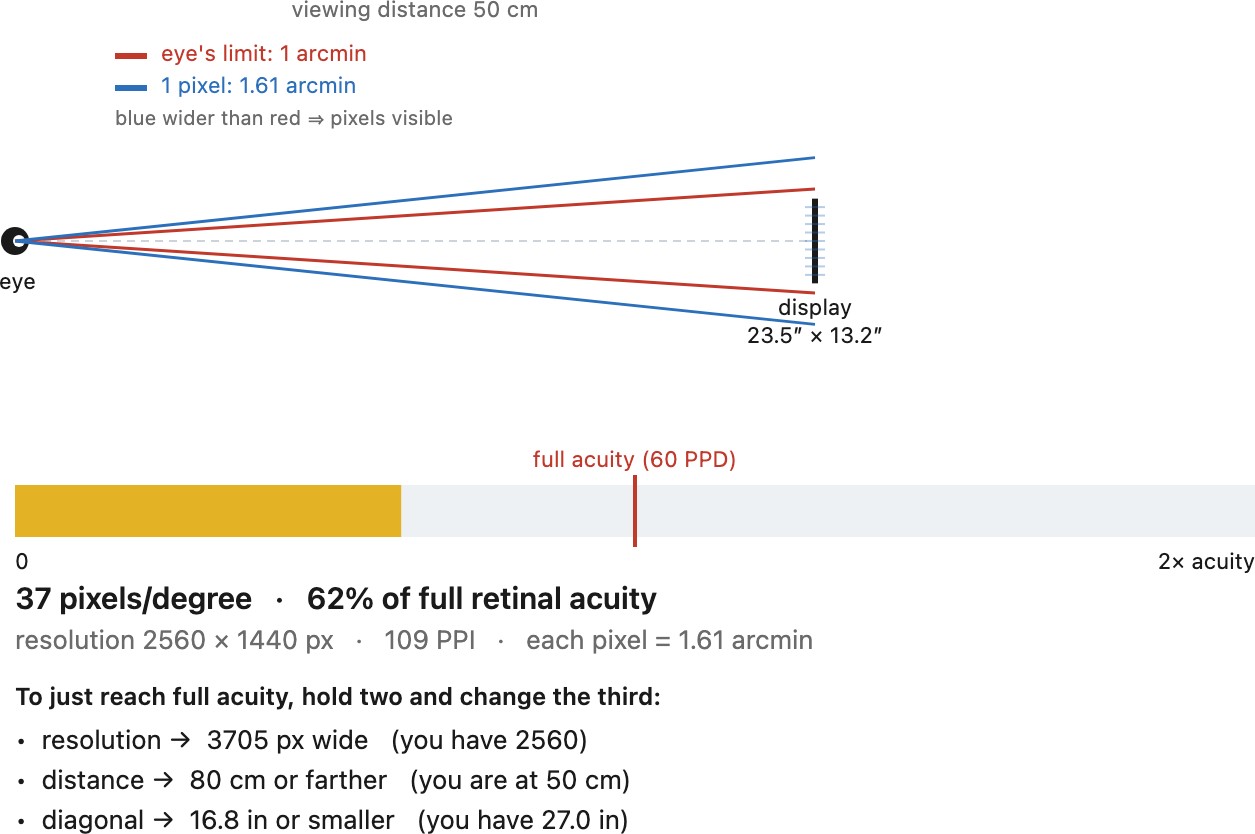
The payoff is a caution about chasing pixels. A 4K television (3840 px across) filling a typical living-room field of view already sits beyond one arcminute per pixel, so at normal distances 8K buys essentially nothing the eye can resolve; the extra pixels matter only if you sit unusually close or the screen is enormous. The same rule sizes the sane resolution for a phone, for a print (viewed close, which is why photo prints target ~300 dots per inch), and for a virtual-reality headset, where the display sits centimeters from the eye and the density demands become brutal (the headset case is taken up in Integral and immersive imaging). Drive the trade-off yourself in the calculator (Figure 2.17.5): fix any two of distance, size, and resolution and read off the third that reaches full acuity, along with what fraction of the eye's limit the display is currently feeding it. This acuity limit is the same 60-cycles-per-degree ceiling that the contrast sensitivity function sets in Human Vision (Spatial vision); a display only needs to out-resolve the eye, never the scene.
2.17.8 Sharpening for the display: size and distance⧉
Acuity does not only decide how many pixels a display needs; it decides how much you should sharpen the image you send to it, and the two are the same physics. Sharpening (the mechanism is unsharp masking, developed in Sharpening) boosts a band of spatial frequencies to make edges read as crisp. Which band matters, because perceived sharpness is not "more high frequencies is better." The eye's contrast sensitivity peaks around 2 to 6 cycles per degree and falls off toward its 60-cycle acuity ceiling (Human Vision, Spatial vision), so an edge looks sharpest when the sharpening puts its extra contrast near that peak as the image is actually viewed. That mapping from image detail to cycles-per-degree depends entirely on the output size and the viewing distance, exactly the geometry of the previous section. The consequence is the single most important rule of output sharpening: sharpen for the output, and judge at the output's size and distance, not at 100% on your monitor unless the 100% monitor view is the delivery.
This is why professional workflows sharpen in more than one pass, the model usually credited to Bruce Fraser. Capture sharpening is a small, fixed correction applied at input resolution to undo the softening every camera bakes in (the anti-aliasing filter, the lens, and demosaicking, per Demosaicking). Creative sharpening is local and to taste, applied to eyes or texture, not the whole frame. Output sharpening is the pass that this section is really about: it is applied last, after the image has been resized to its final pixel dimensions, and it is tuned to the medium and the viewing distance. The radius scales with the output resolution (a wider radius for a big print at 300 ppi than for a 1000-pixel web image), and the amount scales with the medium and distance: matte and watercolor papers need markedly more because ink spreads into the fibres and dulls the very edges you sharpened, glossy paper and screens need less, and an image meant to be seen from far away (a poster, a billboard) tolerates, and wants, heavier sharpening than one held at reading distance. Downsizing for the web is a special trap here: shrinking an image low-passes it (the resampling discussion in the sampling chapter), so a picture that looked crisp at full size comes out soft at 1000 pixels and must be re-sharpened at that size.
The same acuity logic governs the failure mode. Over-sharpening produces halos, bright and dark fringes hugging every strong edge, and whether they are objectionable is itself a viewing-distance question: a halo that screams at 100% on your monitor may be invisible in an 8×10 print held at arm's length, and a print sharpened until it looks slightly crunchy up close can look perfect on a gallery wall seen from three metres. So the discipline is to soft-proof the real output: sharpen while viewing the image at the pixel size and distance it will really be seen, or at a faithful simulation of it, and let the acuity budget of the previous section, not the convenience of the 100% preview, set how hard you push.
2.17.9 Light level viewing conditions⧉
Where an image is looked at changes how it looks, by enough that the encoding has to account for it. Two effects matter most: the absolute light level, and the brightness of the surround around the picture.
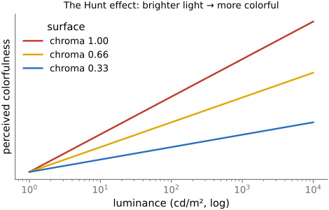
Color appearance shifts with the light level. There is a general blue shift in dim light and a drift in the perceived white point, and colorfulness grows with luminance, the Hunt effect: the same surface looks more vividly colored when brightly lit than when dim, which is why an image on a bright display or in a bright room reads as more saturated (Figure 2.17.6). Hue itself shifts with intensity (the Bezold–Brücke shift) and with added white (the Abney effect). Faithful reproduction therefore cannot just match the numbers; it needs color-appearance models that account for the viewing environment (Fairchild, Color Appearance Models).
The brightness of the surround changes perceived contrast. Against a dark surround the eye's effective contrast drops, so an image looks flatter than the same image would in a bright room. Reproduction media compensate by baking a different end-to-end (system) gamma into each viewing condition. A movie watched in a dark theater is graded and encoded with a relatively high system gamma (around $2.4$–$2.6$) to restore the contrast the dark surround steals; a slide projected in a dim room sits a little lower; a print, or a screen used in a bright room where the surround already lifts perceived contrast, wants a system gamma near $1$ (little or no boost). The same scene, prepared for these three conditions, carries three different tone curves, which is one reason the "gamma" of an imaging system is not a single fixed number but a choice tuned to where the picture will be seen (→ Measuring and encoding color).
2.17.10 Robustness of perspective to the viewer's viewpoint⧉
The last section was about how the light in the room changes a picture's appearance. There is a second, stranger fact about where you stand to look at a picture, and it is geometric rather than photometric. A flat picture reproduces the exact retinal image of the original scene only when your eye sits at one special point, the picture's center of projection (CoP): the place where the taking camera's pinhole effectively was, scaled to the size of the print. Sit exactly there and the rays reaching your eye match the rays the camera gathered, one for one. Sit anywhere else (off to the side, too close, too far) and the geometry no longer matches; the picture becomes an oblique, foreshortened projection of itself, and a strict reading of perspective predicts that it should look distorted. Yet it almost never does. We look at photographs and paintings from wherever we happen to be sitting, essentially never from the CoP, and they look fine. This robustness is not a footnote. It is the quiet precondition that lets pictures be shared at all: a photograph you could view correctly only from one pinpoint in space would be nearly useless.
The foundational claim: compensation. The canonical statement is Pirenne's Optics, Painting and Photography (Pirenne 1970), the reference nearly everything since cites. Pirenne, crediting the core hypothesis to Einstein, argued that when the shape and position of the picture surface can be seen (its frame, its texture, its slant), an unconscious, intuitive process of psychological compensation restores the correct view even when the picture is looked at from the wrong place. The key move is that seeing the surface is what enables the correction: once the visual system registers that the page is a flat sheet tilted at a particular angle in front of you, it can discount that tilt. Kubovy's The Psychology of Perspective and Renaissance Art (Kubovy 1986) is the companion classic, tracing how painters understood and exploited this tolerance for centuries.
The mechanism. The best single modern treatment, and the most useful for a photography audience, is Vishwanath, Girshick and Banks, Why pictures look right when viewed from the wrong place (Vishwanath et al. 2005). They measured perceived shape across a wide range of oblique viewing angles while manipulating the information available about the picture surface's orientation. The finding is clean: when binocular cues to the surface's slant were available, perceived shape was nearly invariant across a wide span of viewing angles, and perceived shape turned out to be determined by more than the light striking the eye; it also depends on the sensed orientation of the picture surface. That is the mechanistic core of compensation. The visual system estimates the slant of the picture plane, infers where the center of projection must therefore be, and reinterprets the retinal image as if it were seen from that recovered CoP. Robustness is not the eye ignoring the distortion; it is the eye actively undoing it using its estimate of how the page is tilted.
But compensation is real and imperfect. It would be easy to overstate the effect, so the corrective literature matters. Perkins gave an early empirical treatment of compensation for oblique viewing (Perkins 1973). Yang and Kubovy then weakened the strong claim (Yang & Kubovy 1999): observers neither fully compensate for nor fully experience the transformations geometry predicts, and they demonstrated a "cuboid illusion" in which the percept does systematically depend on the picture's orientation and position even when surface cues are abundant, contradicting a strong reading of Pirenne. Todorović's direct skeptical tests reach the same verdict (Todorović 2008): pictorial perception is only partly robust. Koenderink, van Doorn and colleagues (Koenderink et al. 2004, and later work) argue more broadly that pictorial space is its own thing, a mental construct with its own rules rather than a faithful reconstruction of the scene's true geometry. (For the older reviews, see Hagen on picture surface and station point (Hagen 1976) and Rosinski and Farber's chapter (Rosinski & Farber 1980).) The honest summary is that compensation buys a great deal of slack, but not infinite slack, and it fails in measurable, repeatable ways.
Where the field is now. The current account, and the most useful one for this book, is Hertzmann's (Hertzmann 2024, with the empirical follow-up Martin et al. 2025). Hertzmann argues that the whole vantage-point-compensation framing is inadequate and proposes fixation-centered perspective: shape and space in a picture are interpreted according to a linear projection centered on the viewer's current fixation, and distortion is perceived when a shape is depicted inconsistently with that locally-linear perspective. This is the freshest and most directly useful account here, because it explains the wide-angle phenomena the rest of this book cares about. It is why faces at the edge of a wide-angle frame look stretched (they violate the perspective the eye expects around the point it is looking at), and why classical painters, per Pirenne and Kubovy, drew spheres and faces as if the principal point had been moved to each object's own center: locally correct perspective, object by object, which is exactly what fixation-centered perception rewards.
Why this belongs in a computational-photography book. The arc is clean. Pirenne's robustness is what lets photography work at all, since pictures are then viewable from anywhere and not only from the CoP. Vishwanath et al. give the mechanism (estimate surface slant, recover the CoP, reinterpret). Yang and Kubovy and Todorović bound it: compensation is partial and fails predictably. And the failures are precisely where computational photography steps in. Wide-angle portrait distortion is the case compensation does not rescue, because the viewer is nowhere near the CoP of a very short lens and the depicted faces violate the fixation-centered expectation. So the content-aware corrections of Perspective distortion and its correction (Carroll's content-preserving projections, Shih's distortion-free portraits, and MaDCoW's per-object local perspective) are, in effect, engineering around the limits of vantage-point compensation. Perception and the algorithms are two halves of one story, and reading them together is a far better account than treating either in isolation.
2.17.11 Gamut and gamut mapping⧉
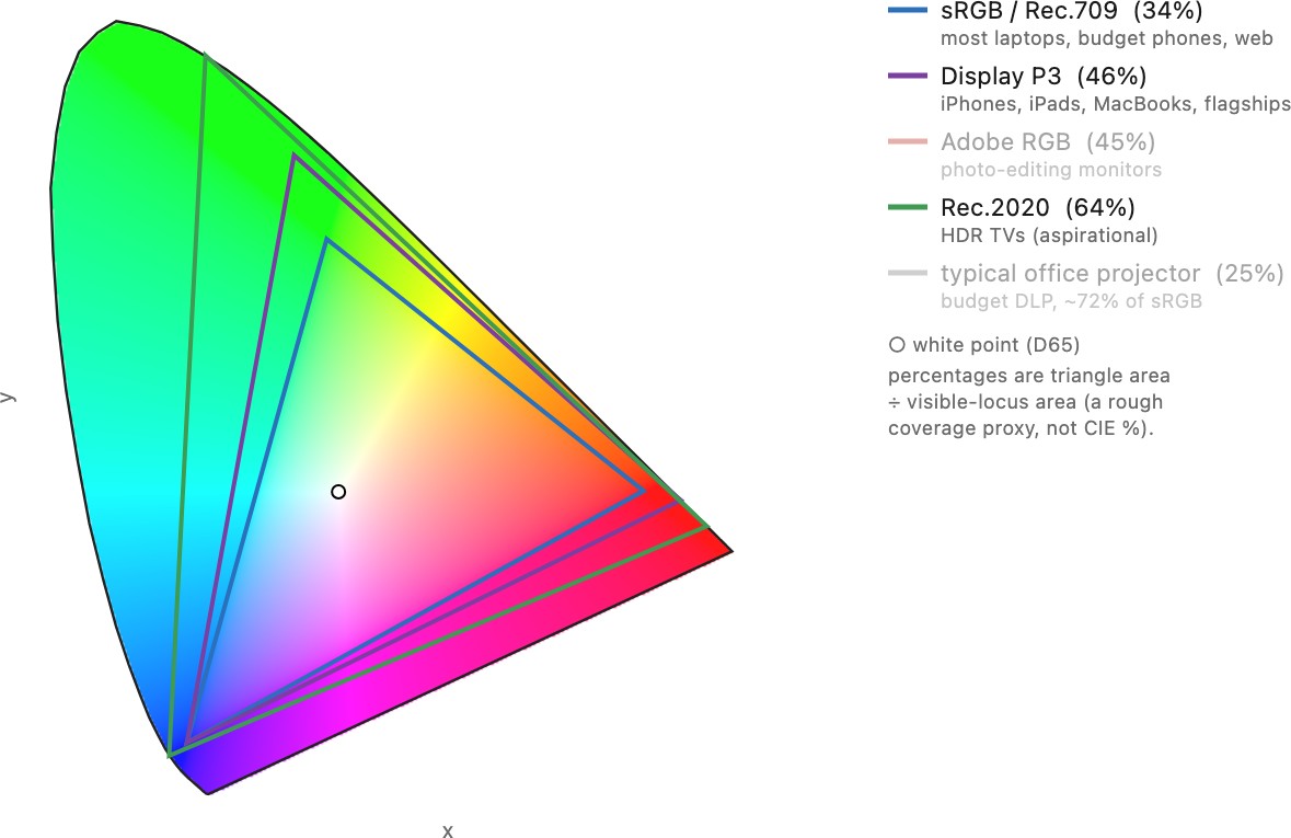
A display cannot make every color the eye can see. Its three primaries are three fixed points on the CIE chromaticity diagram, and every color it can produce is a mix of them, so the reachable set is the triangle those three points span (Figure 2.17.9). That triangle is the display's gamut. The eye's whole visible range is the horseshoe-shaped spectral locus that encloses it, and no triangle inscribed in that curved boundary can cover it, because the boundary is curved and a triangle has straight sides. Every real device therefore sees only a slice of what the eye does, and the more saturated the color, the more likely it falls outside. Wider-gamut standards (Adobe RGB, Display P3, Rec.2020) push the primaries outward toward the spectral locus and enlarge the triangle, but none reaches the whole horseshoe, and pushing the primaries out has its own cost: the same 8 bits now have to span a larger volume, so the color steps between adjacent codes grow, which is one reason wide-gamut content wants more bits per channel. These standards are not abstractions: they are the gamuts real devices target, and they differ enough that the same color numbers land on visibly different colors from one to the next (Figure 2.17.8).
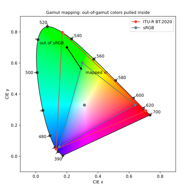
The practical problem appears whenever an image is prepared in one gamut and shown in a smaller one: a photograph graded on a Display P3 monitor, sent to an sRGB screen or a print. The out-of-gamut colors, the ones outside the destination triangle, cannot be reproduced, so something has to be done with them. Doing nothing is not an option, because the display will clip them to its boundary in whatever crude way the hardware happens to, usually by saturating one channel and shifting the hue. Gamut mapping is the deliberate choice of how to bring those colors in, and there is no free lunch: any mapping loses information, and the only question is which loss looks least wrong.
Three strategies bracket the space (Figure 2.17.9). The simplest is to clip each out-of-gamut color to the nearest point on the destination boundary. It is cheap and leaves in-gamut colors untouched, but it flattens saturated detail: a range of vivid colors all collapse onto the same edge, so gradients band and texture in the saturated regions disappears. Clipping toward the boundary can also shift hue, since the nearest boundary point is not always in the same hue direction. A hue-preserving variant is to clip toward the white point: pull each out-of-gamut color straight in along the line to white until it reaches the destination boundary, which drops chroma (saturation) while keeping hue and roughly keeping lightness. The opposite philosophy is to compress the entire gamut inward, scaling every color, including the ones already inside, so that the relationships between colors survive: a smooth gradient stays smooth, and nothing bands, at the cost of desaturating colors that would have reproduced fine. Clipping preserves accuracy for most of the image and sacrifices the extremes; compression preserves the extremes' relative structure and sacrifices exactness everywhere. Photographs, where continuity of gradients matters more than exact saturation, usually want compression; a logo or a spot color, where the exact hue matters, usually wants clipping. Good gamut-mapping algorithms work in a perceptually uniform space (CIELAB or a color-appearance space) rather than raw chromaticity, so that "nearest" and "keep the relationships" mean nearest and proportional to the eye, and the best of them are spatial, adapting the mapping to local image content rather than treating every pixel independently.
These are exactly the choices the ICC formalizes as rendering intents in the next section: relative colorimetric is clipping (leave in-gamut colors alone, map the rest to the boundary), and perceptual is compression (scale the whole gamut to fit). Gamut mapping is where the abstract fact that a display has a limited gamut turns into a concrete decision about individual pixels.
2.17.12 Color management, ICC, and industry standards⧉
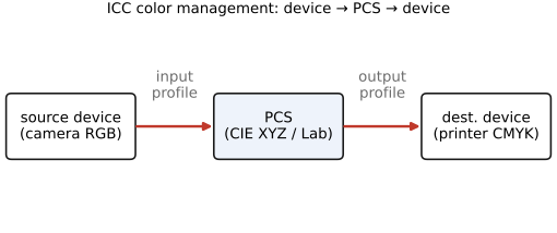
A color on a display is a triple in some space, but a naked triple is ambiguous: the same numbers $(200, 50, 50)$ are a different red on every device, because each camera, monitor, and printer has its own primaries, white point, gamut, and transfer curve. The result is the everyday complaint that a photo looks different on the screen than in the print. The solution is color management, standardized by the ICC (International Color Consortium). Each device carries a profile that maps its values to and from a device-independent profile-connection space (PCS), which is $XYZ$ or CIELAB (Figure 2.17.10). To move an image from camera to printer you go device → PCS → device: convert the camera's numbers into the absolute PCS, then out into the printer's numbers. The PCS is the lingua franca that makes color portable.
When the destination gamut is smaller than the source (gamut mapping, Measuring and encoding color), the profile must decide what to do with out-of-gamut colors, and ICC offers four rendering intents: perceptual (compress the whole gamut inward, preserving relationships — good for photographs), relative colorimetric (leave in-gamut colors untouched, clip the rest, and match white points — good for most prints), saturation (favor vividness over accuracy — for charts and graphics), and absolute colorimetric (reproduce exact colors including the paper white — for proofing). A second job profiles handle is chromatic adaptation between differing white points, computed with a Bradford $3 \times 3$ transform (Bradford chromatic-adaptation transform) — the engineering descendant of the von Kries adaptation from the perception chapter, and the same machinery reused for white balance in Auto-exposure and auto white balance (BASIC). In practice, profiles are embedded in image files, monitors are calibrated against a reference, soft-proofing previews the print on screen, and sRGB serves as the safe default whenever a file arrives with no profile attached.