2.7 Lens Image formation⧉
A pinhole forms an image by throwing away almost all the light; only the rays through the tiny hole survive. That is a serious problem: a pinhole sharp enough to make a crisp image passes so little light that exposures take seconds, and (as the previous part's diffraction limit warned) shrinking the hole eventually blurs the image anyway. We want to collect a wide cone of light from each scene point, far more light than a pinhole, and still focus it to a single image point. That is exactly what a lens does, and the price it charges is a single plane of focus and a finite depth of field.
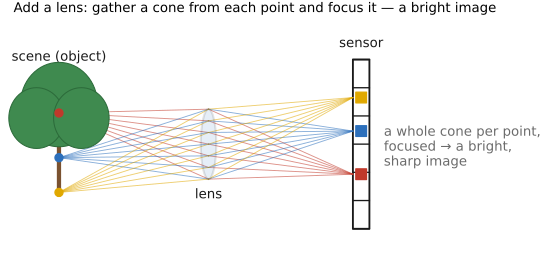
The two image-formation playgrounds from the pinhole chapter (Figures 2.4.4 and 2.4.5) return here, now opened on the thick lens rather than the bare sensor. They carry the same four scenarios as before (bare sensor, pinhole, thin lens, thick lens); flip between them and notice how much brighter and sharper the lens images are than the pinhole's, and far more so than the bare sensor's flat average. The lens earns that by gathering a whole cone of rays from each point instead of the single ray a pinhole keeps.
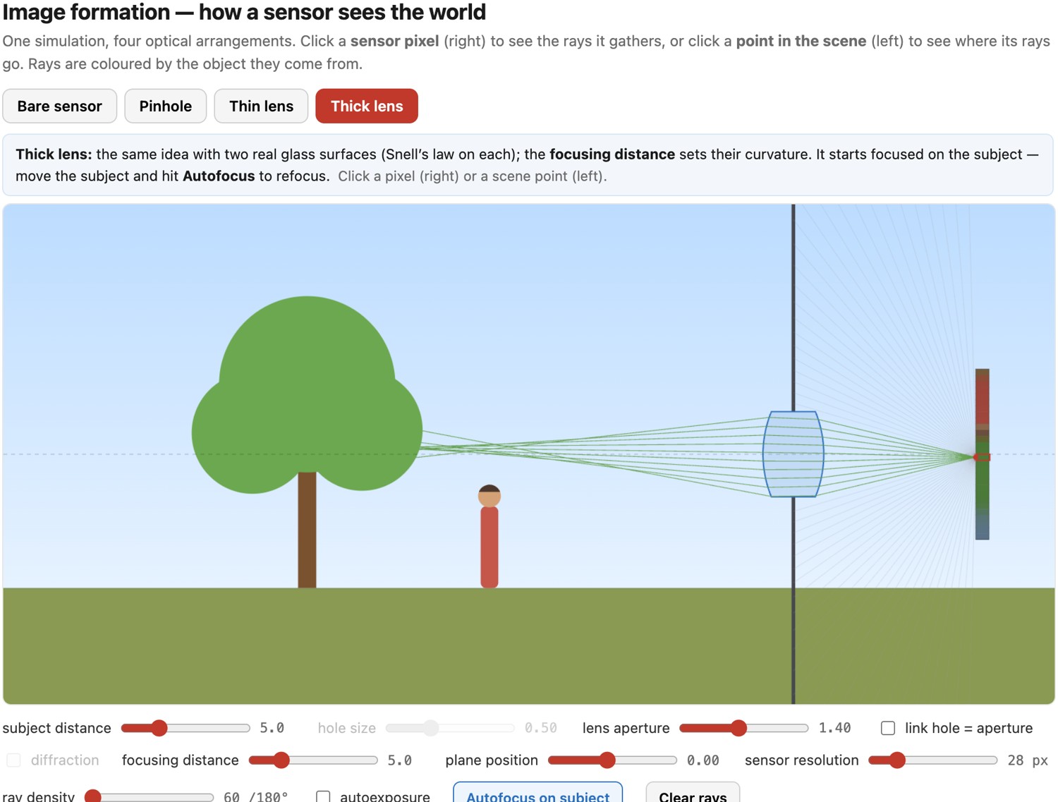
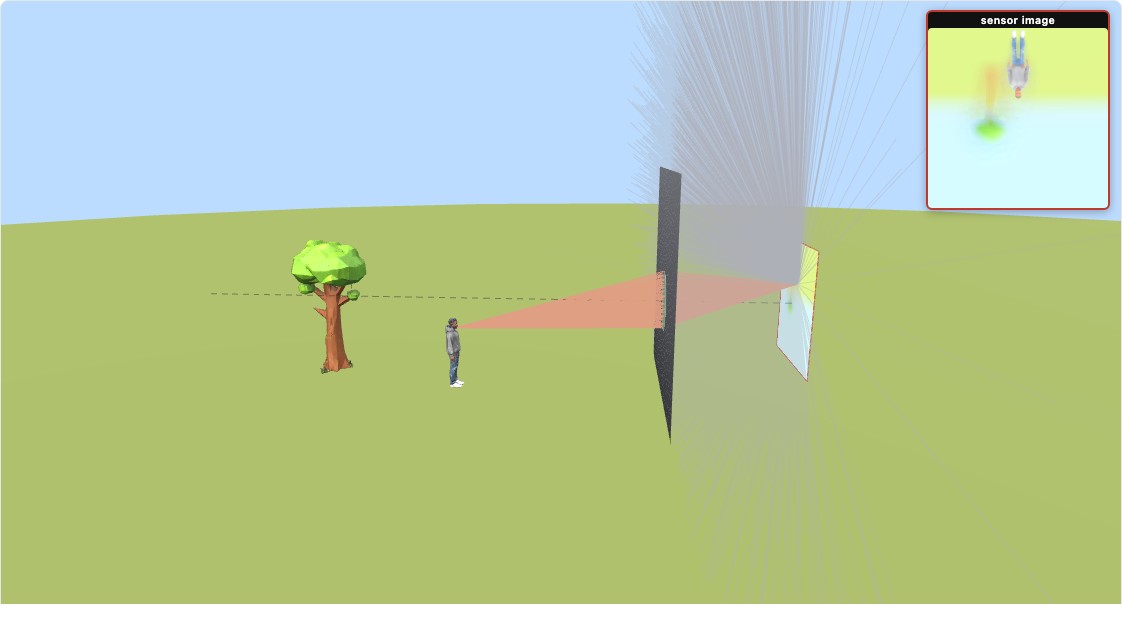
Recall the framing from the pinhole chapter: image formation is about choosing which rays contribute to each image point (→ see Big lesson L2.20). The pinhole answered with one ray per point; the lens gives a richer answer, and it is worth stating as its own lesson.
Where a pinhole keeps only one ray, a lens gathers the whole cone of rays leaving a scene point and bends them back to a single image point, but only for points at the focus distance. That is the lens's bargain: vastly more light (a bright image) in exchange for a single plane of sharp focus, with everything nearer or farther spread into a blur disk (the circle of confusion). The aperture sets how wide that cone is, and hence the depth of field. Every later idea about focus, bokeh, refocusing, and light fields is a variation on "which cone of rays reconverges where."
This chapter follows that bargain in three steps. First, a single lens bending light by refraction: Snell's law at two curved surfaces, with the Fermat "equal optical path" view alongside. Then the thin lens: the small-angle linearization of that law that hands us the focus equation, conjugates, magnification, and the f-number in a few clean lines. Finally depth of field: the range of distances a single focus plane keeps acceptably sharp, the circle of confusion that defines it, and the surprising fact that (at fixed framing) it barely depends on focal length at all. Throughout, we are using the paraxial model; what it throws away (aberrations, color) points forward to the OPTICS part.
2.7.1 Single lenses: refraction and Snell's law⧉
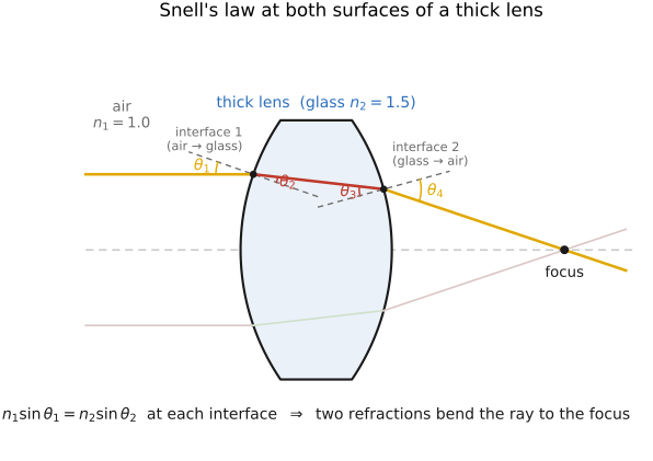
A real lens is a piece of glass bounded by two curved surfaces, that is, two interfaces: air-to-glass and glass-to-air. It works by refraction: the bending of light as it crosses between media of different refractive index, introduced in Light and physics. At each interface a ray bends according to Snell's law (Descartes' law, if you are French):
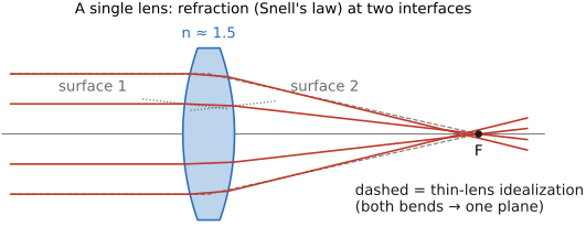
where $n_1, n_2$ are the refractive indices on the two sides and $\theta_1, \theta_2$ the angles measured from the surface normal. Drawn on a deliberately thick lens, with the two interfaces far apart, you can watch the bending happen twice (once entering the glass, once leaving) and the net effect of the two curved surfaces is to steer a parallel bundle of rays so they converge to a focal point (Figures 2 and 3). A curved interface bends each ray by an amount that depends on where it strikes the surface, and the curvature is chosen so that all the rays from one scene point are redirected to meet at one image point. That is the whole job of a lens: bend a wide cone back to a point.
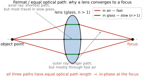
A second, equivalent view: Fermat and equal path lengths. There is a wave-side way to see why a lens focuses, worth holding alongside the ray picture because it explains why the curvature has to be just so. A lens focuses because every ray from the object to the focus travels the same optical path length, geometric distance weighted by the refractive index of each medium it crosses (Figure 2.7.10). A ray through the thick center of the lens takes a longer geometric path but spends more of it in slow glass; a ray skimming the thin edge takes a shorter geometric path, almost entirely through fast air. The lens's shape is exactly what makes these trade off perfectly, so all the rays arrive at the focus in phase and interfere constructively, building a bright point. Snell's law (rays bending) and Fermat's principle (equal optical paths) are two descriptions of the one fact; either predicts the same focus.
How strongly a lens bends light (its focal length) is set by the curvature of its two surfaces and the glass index, through the lensmaker's equation:
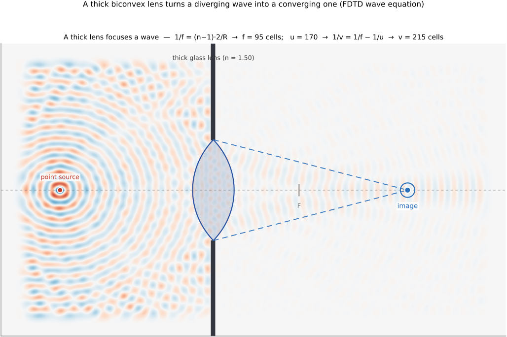
with $R_1, R_2$ the radii of curvature of the two surfaces. More curvature, or a higher index, means a shorter focal length (stronger bending). We can watch this happen directly by solving the wave equation: send a point source's diverging wave into a slab of glass and let the wave evolve (Figure 2.7.8). Because the glass is thickest on the axis, it slows the middle of each wavefront most, and that is exactly enough to bend a diverging wavefront into a converging one, which collapses to an image point on the far side. The focus lands where the lensmaker's and imaging equations say it should, and tightening the curvature or raising the index pulls it inward, just as $1/f=(n-1)\,2/R$ predicts.
This whole picture, though, already assumes the rays make small angles with the axis: it is paraxial. At large angles the rays from a single point do not all meet at exactly one place, and the image degrades; those departures are aberrations, the subject of the OPTICS part, where compound lenses (many elements) are designed to cancel them. Our own eyes are refracting systems too: the cornea and the lens are the two main bending elements, doing for the retina what a camera lens does for the sensor.
2.7.2 Thin lens optics⧉
The two-interface, Snell's-law lens is accurate but cumbersome. For everything in this book except the dedicated optics chapters, we replace it with a linearization called the thin lens, and two assumptions do all the work. First, the rays stay near the axis and make only small angles, so Snell's law can be linearized: for small $\theta$, $\sin\theta\approx\theta$, the angle and its sine agree and the bending becomes proportional to the angle. Second, the lens is thin enough that we can ignore how far the light travels inside the glass, so both refractions collapse into a single bend at one plane.
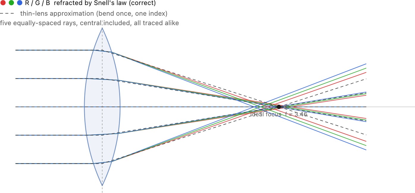
Be candid about what that buys and what it costs (Figure 2.7.9). The small-angle (paraxial) swap is exactly why the focus equation $\tfrac{1}{f}=\tfrac{1}{u}+\tfrac{1}{v}$ (below) comes out so clean, and why "every ray from one object point converges to one image point" is true in the model: with $\sin\theta\approx\theta$ a single object point images to a single, perfectly sharp point (stigmatic imaging), and a parallel bundle from infinity converges to one point in the focal plane. A real lens only approximates this. Rays that wander too far from the axis miss the ideal point, the departures we call aberrations (spherical aberration, coma, and the rest). And the model drops color: the real index $n$ varies with wavelength (dispersion), so red and blue bend by slightly different amounts and focus in slightly different places (chromatic aberration), while the thin lens pretends every wavelength shares one $n$ and one focus. So the thin lens is a convenient lie, linearizing Snell's law and throwing away color, accurate enough that the whole rest of the book leans on it and wrong in precisely the ways the OPTICS chapters spend their time correcting.
The image-formation figures at the start of this chapter make this payoff tangible: put Figure 2.7.2 or Figure 2.7.3 on the thin or thick lens and click a point to watch its whole cone of rays reconverge onto a single pixel, far brighter than the pinhole's lone ray.
What we just did to Snell's law is one of the most powerful moves in all of physics and engineering, and it is worth naming as a general tool, because the book will reach for it again and again. Replace a messy nonlinear function by its tangent line near the operating point, keep only the first-order (linear) term of its Taylor expansion, and it is an excellent approximation as long as the relevant quantity stays small. Here the small quantity is the angle, $\sin\theta\approx\theta$, and the reward is the entire clean, linear machinery of paraxial optics. The same reflex linearizes brightness change into the optical-flow constraint (a chapter away), drives the Gauss–Newton steps of lens optimization and bundle adjustment, and propagates small noise through a pipeline. Two disciplines keep it sound. Know when it breaks: the approximation is only as good as the terms you dropped are negligible, so always ask "how small is small?" And keep the next term in your pocket: restoring it is not a footnote but a whole theory: for optics that next term is the cubic $-\theta^3/6$, and restoring it is the study of aberrations (next big lesson, and the OPTICS part).
The clean thin-lens equation $1/f = 1/u + 1/v$ is not a separate law: it is Snell's law (L2.4) linearized, kept to first order under the small-angle approximation $\sin\theta\approx\theta$, the regime known as paraxial (rays near the axis, gentle angles, one wavelength). Because it keeps only the linear term, it tells you exactly when the idealization holds and exactly how it breaks: restore the next term $\sin\theta\approx\theta-\theta^3/6$ and the Seidel aberrations appear; let $n$ vary with wavelength and chromatic aberration appears. "Thin lens," "first-order optics," "a linear (paraxial) lens," and "a lens with no aberrations" are all the same approximation, and the OPTICS part is the story of paying back what it borrowed.
Under these two assumptions the geometry collapses to bending at a single plane, and two construction rules locate any image:
- A ray arriving parallel to the axis leaves through the focal point $F$, at distance $f$.
- A ray through the center of the lens passes undeviated, straight through, as through a pinhole. (This second rule is why a thin lens has the same perspective as a pinhole: the central ray is the chief ray, so the projection geometry of the previous chapter carries over unchanged. The lens only adds light-gathering and focus on top of pinhole projection.)
Parallel rays through a thin lens converge to a point at the focal length, and rays going through the center of a thin lens do not deviate. The first rule is what focal length means (where a far subject's parallel bundle meets) and carries the lens's focusing power; the second carries its perspective, identical to the pinhole's. Between these two construction rules and similar triangles, you can derive all of thin-lens optics.
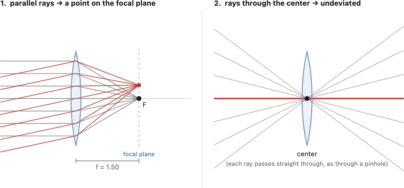
The thin lens is precisely first-order (paraxial) optics: replace $\sin\theta \approx \theta$, keeping only the linear term of the sine. Keep the next term, $\sin\theta \approx \theta - \theta^3/6$ (third-order optics), and out pop the classical Seidel aberrations: spherical aberration, coma, astigmatism, and the rest. So "the thin-lens linearization" and "a lens with no aberrations" are literally the same assumption, dropped at the same place. The OPTICS part keeps the cubic term.
The focus equation. Place an object at distance $u$ in front of the lens; its sharp image forms at distance $v$ behind, and the two are tied by the thin-lens (conjugate) equation:
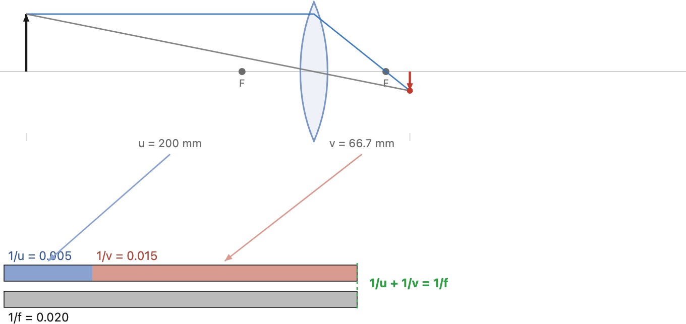
The thin-lens equation $\tfrac{1}{u}+\tfrac{1}{v}=\tfrac{1}{f}$ is symmetric in $u$ and $v$: swap them and it is unchanged, so object and image are interchangeable. Send the light back the other way and the rays retrace exactly the same path (the reversibility of light, made arithmetic). Two consequences fall straight out: an object at infinity images at $v=f$, which is what focal length means, and focusing a camera is nothing but moving $v$ until the chosen object's conjugate lands on the sensor.
The most basic way to focus follows straight from the equation: move the whole lens relative to the sensor, changing the lens-to-sensor distance $v$ until the chosen subject's conjugate lands on the sensor. This is full or unit focusing, the entire optical unit sliding with its focal length fixed. A bellows, the helicoid focus ring on a simple prime, and a bare enlarger lens all work this way, and it is the mental model to keep. It is only the simplest option, though. A compound lens has many elements, and moving just some of them (front-cell, internal, or rear focusing, sometimes with floating groups) can focus while extending the barrel less, holding aberrations in check across the focus range, or even nudging the effective focal length. Those techniques, and why designers reach for them, come in the OPTICS part's focus section.
Read it back: the reciprocals of the object and image distances add to the reciprocal of the focal length. An object at infinity ($1/u \to 0$) images at exactly $v = f$: that is what "focal length" means for a lens, the image distance for a far subject. As the object comes closer, $1/u$ grows, so $1/v$ must shrink: the image moves farther back. Focusing a camera is nothing more than adjusting $v$ (moving the lens, or the sensor) until the image of the subject you care about lands exactly on the sensor (Figure 2.7.12). Each object distance has exactly one image distance that focuses it (they are conjugates) and an object placed right at the focal point $F$ sends out rays that exit parallel, imaging at infinity (the reverse of the first case).
Symmetry and reversibility. Notice that the focus equation is symmetric in the two distances: writing it $1/f = 1/s_o + 1/s_i$, with $s_o$ the object distance and $s_i$ the image distance, nothing distinguishes the two: swap them and the equation is unchanged. This is no accident; it is the reversibility of light paths made arithmetic. Object and image are conjugate: send light the other way, and the rays retrace exactly the same path, so the old image plane now acts as object and the old object plane as image. The two are conjugate planes, and the magnification swaps with them: $m = -s_i/s_o$ simply inverts ($m \to 1/m$) when you exchange the roles. This object↔image reciprocity runs all through optics: it is why a lens images perfectly well either way round, and (a case we meet in the OPTICS part) why a lens's entrance and exit pupils are themselves conjugates: images of the same aperture seen from the two sides.
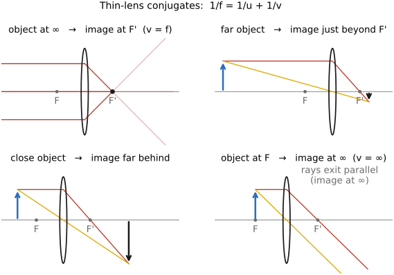
The image is inverted and resized; the magnification is
the ratio of image to object distance (the minus sign records the flip).
Magnification is the size of a subject's image divided by the subject's actual size in world units (meters): $m = -v/u$ is exactly that ratio (image height over object height). Photographers quote it as a reproduction ratio: 1:1 ("life size") means the image on the sensor is as large as the subject itself; 1:2 means half life size. Crucially, what fraction of the frame a subject then occupies depends on the sensor size: the same magnification fills more of a small sensor than a large one. On a full-frame ($24\times36$ mm) camera a $1{:}2$ reproduction images a subject about $48\times72$ mm to exactly fill the frame; put that same subject on a smaller sensor at the same magnification and it overflows. So magnification is a property of the optics-and-distance alone, while "how big it looks in the picture" also needs the sensor size.
Finally, the lens has an aperture (the diameter $D$ of the opening that admits light) and photographers describe it not by $D$ directly but by the f-number
the ratio of focal length to aperture diameter. A small f-number ($f/1.4$) is a wide opening; a large one ($f/16$) is a narrow opening: the number is under the divider, so it runs backwards from how much light gets through. The f-number controls two things at once, exposure and blur. We meet the blur in the Depth of field chapter next; the aperture and the f-number get a fuller treatment at the end of this chapter (why the ratio makes brightness portable, and the $\sqrt2$ stop series), and the exposure practice built on it is taken up in Exposure.
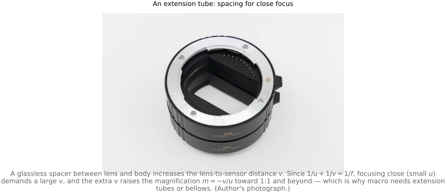
The same focus equation quietly explains why macro photography is hard. Rewrite it as $1/v = 1/f - 1/u$: to focus a close subject, $u$ shrinks, so $1/u$ grows, so $1/v$ has to shrink, which means $v$, the lens-to-sensor distance, has to grow. High magnification is the same statement, since $m=-v/u$: getting to 1:1 (life size) requires $v=u=2f$, twice the infinity-focus distance, and going beyond 1:1 pushes $v$ larger still. An ordinary lens simply cannot rack its focusing helicoid out that far. The fix is to physically move the lens farther from the sensor, which is exactly what an extension tube (a hollow, glassless spacer) or a bellows (a continuously adjustable one) does (Figure 2.7.13): they add nothing optical, they just buy the large $v$ the equation demands. This is also why a lens's closest focus distance and its maximum magnification are the same spec seen two ways, and why dedicated macro lenses build long focusing extensions into the barrel.
2.7.3 Aperture and the f-number⧉
We met the f-number $N = f/D$ a moment ago; it is worth a section of its own, because it is one of the few numbers a photographer touches every time they shoot, and because why it is written as a ratio is genuinely illuminating. The aperture is a physical thing, the diameter $D$ of the opening that admits light. Yet lenses are never marked in millimetres of opening; they are marked $f/2.8$, $f/5.6$, $f/11$, the focal length divided by that diameter. The slash is literal: $f/2.8$ means "the focal length, split into 2.8," an opening $D = f/2.8$ wide. Because $D$ sits in the denominator, the scale runs backwards from intuition, a small f-number is a wide opening (lots of light, shallow depth of field) and a large f-number is a narrow one. Once you internalize that the number is a divisor, "$f/1.4$ is bright and $f/22$ is dim" stops feeling backwards.
Why quote the opening as a fraction of focal length at all, rather than its raw diameter? Because the fraction, not the diameter, is what fixes the brightness of the image. The light delivered to a point on the sensor arrives as a cone: the rays that clear the aperture and reconverge there. The wider that cone, the more light. Its half-angle $\theta$ satisfies $\tan\theta = (D/2)/f = 1/(2N)$, so the cone depends only on the ratio $N$, never on the focal length by itself (Figure 2.7.14). Double the focal length and double the diameter, and the opening is physically twice as big, yet the cone, and therefore the brightness, is unchanged, because $N$ is unchanged. This is the whole reason the ratio exists: it makes a brightness setting that transfers. Set any lens to $f/2.8$, a $24$ mm or a $600$ mm, and each throws the same irradiance onto the sensor, even though the $600$ mm's opening is enormous by comparison. A raw diameter could never do that; the ratio nets out the focal length exactly. (The transfer is only mostly exact: vignetting darkens the corners, oblique rays fall off toward the frame edge, and at close focus the effective f-number opens up to $N_\text{eff} = N(1+m)$ with magnification $m$, the "bellows factor" behind macro's light loss. The geometry above is the clean first-order truth those are corrections to.)
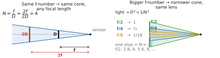
The same cone picture explains the aperture scale's strange-looking numbers, $f/1.4, f/2, f/2.8, f/4, f/5.6, f/8, f/11, f/16$, a march in steps of $\sqrt2$. Light gathered goes as the opening's area, which goes as the diameter squared, so at a fixed focal length the light scales as $D^2 \propto (f/N)^2 \propto 1/N^2$. A stop, photography's unit, is a factor of two in light. To halve the light you must halve the area, and halving an area means shrinking the diameter by $\sqrt2$, i.e. multiplying $N$ by $\sqrt2$. That is the entire origin of the series: each full stop is one $\sqrt2$ step in f-number and one factor of two in light (the figure; and panel B of Figure 2.7.14). It is why the numbers look irregular but are really a clean geometric progression, and why aperture, shutter, and ISO can all be counted in the same stops (the exposure triangle of Exposure).
$N = f/D$: the f-number tells you the width of the opening measured in focal lengths, not in millimetres. $f/4$ means the opening is one quarter of the focal length across. Writing the aperture this way is what makes it a portable brightness setting: because the cone of light converging on each sensor point has half-angle $\tan\theta = 1/(2N)$, the ratio alone sets the image brightness, so the same f-number gives the same exposure on any lens, whatever its focal length or physical size. The denominator is why a small number is a big opening, and the area-goes-as-diameter-squared law ($\text{light}\propto 1/N^2$) is why the stop series climbs by $\sqrt2$.
Finally, a caveat that matters when light is precious. The f-number is a purely geometric quantity: it assumes a perfect, lossless lens and predicts the light such a lens would gather. Real glass is not lossless, every air-to-glass surface reflects a little, the elements absorb a little, and a complex zoom with twenty elements can quietly swallow up to a stop before any light reaches the sensor. The T-stop (transmission stop) folds those losses in, the f-number of an ideal lossless lens passing the same light, $T = N/\sqrt{\tau}$ for transmittance $\tau$, so a lens engraved $f/2.0$ may test at $T/2.3$. Stills photographers can ignore the difference; cinematographers, who must intercut shots from different lenses at a matched brightness, buy lenses marked in T-stops. The full treatment, and why it matters for metering, is in Exposure (f-stops versus T-stops).
Recap: big lessons of this chapter
Where a pinhole keeps only one ray, a lens gathers the whole cone of rays leaving a scene point and bends them back to a single image point, but only for points at the focus distance. That is the lens's bargain: vastly more light (a bright image) in exchange for a single plane of sharp focus, with everything nearer or farther spread into a blur disk (the circle of confusion). The aperture sets how wide that cone is, and hence the depth of field. Every later idea about focus, bokeh, refocusing, and light fields is a variation on "which cone of rays reconverges where."
What we just did to Snell's law is one of the most powerful moves in all of physics and engineering, and it is worth naming as a general tool, because the book will reach for it again and again. Replace a messy nonlinear function by its tangent line near the operating point, keep only the first-order (linear) term of its Taylor expansion, and it is an excellent approximation as long as the relevant quantity stays small. Here the small quantity is the angle, $\sin\theta\approx\theta$, and the reward is the entire clean, linear machinery of paraxial optics. The same reflex linearizes brightness change into the optical-flow constraint (a chapter away), drives the Gauss–Newton steps of lens optimization and bundle adjustment, and propagates small noise through a pipeline. Two disciplines keep it sound. Know when it breaks: the approximation is only as good as the terms you dropped are negligible, so always ask "how small is small?" And keep the next term in your pocket: restoring it is not a footnote but a whole theory: for optics that next term is the cubic $-\theta^3/6$, and restoring it is the study of aberrations (next big lesson, and the OPTICS part).
The clean thin-lens equation $1/f = 1/u + 1/v$ is not a separate law: it is Snell's law (L2.4) linearized, kept to first order under the small-angle approximation $\sin\theta\approx\theta$, the regime known as paraxial (rays near the axis, gentle angles, one wavelength). Because it keeps only the linear term, it tells you exactly when the idealization holds and exactly how it breaks: restore the next term $\sin\theta\approx\theta-\theta^3/6$ and the Seidel aberrations appear; let $n$ vary with wavelength and chromatic aberration appears. "Thin lens," "first-order optics," "a linear (paraxial) lens," and "a lens with no aberrations" are all the same approximation, and the OPTICS part is the story of paying back what it borrowed.
Parallel rays through a thin lens converge to a point at the focal length, and rays going through the center of a thin lens do not deviate. The first rule is what focal length means (where a far subject's parallel bundle meets) and carries the lens's focusing power; the second carries its perspective, identical to the pinhole's. Between these two construction rules and similar triangles, you can derive all of thin-lens optics.
The thin-lens equation $\tfrac{1}{u}+\tfrac{1}{v}=\tfrac{1}{f}$ is symmetric in $u$ and $v$: swap them and it is unchanged, so object and image are interchangeable. Send the light back the other way and the rays retrace exactly the same path (the reversibility of light, made arithmetic). Two consequences fall straight out: an object at infinity images at $v=f$, which is what focal length means, and focusing a camera is nothing but moving $v$ until the chosen object's conjugate lands on the sensor.
The most basic way to focus follows straight from the equation: move the whole lens relative to the sensor, changing the lens-to-sensor distance $v$ until the chosen subject's conjugate lands on the sensor. This is full or unit focusing, the entire optical unit sliding with its focal length fixed. A bellows, the helicoid focus ring on a simple prime, and a bare enlarger lens all work this way, and it is the mental model to keep. It is only the simplest option, though. A compound lens has many elements, and moving just some of them (front-cell, internal, or rear focusing, sometimes with floating groups) can focus while extending the barrel less, holding aberrations in check across the focus range, or even nudging the effective focal length. Those techniques, and why designers reach for them, come in the OPTICS part's focus section.
Magnification is the size of a subject's image divided by the subject's actual size in world units (meters): $m = -v/u$ is exactly that ratio (image height over object height). Photographers quote it as a reproduction ratio: 1:1 ("life size") means the image on the sensor is as large as the subject itself; 1:2 means half life size. Crucially, what fraction of the frame a subject then occupies depends on the sensor size: the same magnification fills more of a small sensor than a large one. On a full-frame ($24\times36$ mm) camera a $1{:}2$ reproduction images a subject about $48\times72$ mm to exactly fill the frame; put that same subject on a smaller sensor at the same magnification and it overflows. So magnification is a property of the optics-and-distance alone, while "how big it looks in the picture" also needs the sensor size.
$N = f/D$: the f-number tells you the width of the opening measured in focal lengths, not in millimetres. $f/4$ means the opening is one quarter of the focal length across. Writing the aperture this way is what makes it a portable brightness setting: because the cone of light converging on each sensor point has half-angle $\tan\theta = 1/(2N)$, the ratio alone sets the image brightness, so the same f-number gives the same exposure on any lens, whatever its focal length or physical size. The denominator is why a small number is a big opening, and the area-goes-as-diameter-squared law ($\text{light}\propto 1/N^2$) is why the stop series climbs by $\sqrt2$.